EasyManua.ls Logo

Tascam DA-30 - 4. Electrical Adjustments; 4-1. Adjustment of the Servo System

Tascam DA-30
63 pages
Print Icon
To Next Page IconTo Next Page
To Previous Page IconTo Previous Page
Loading...
4.
ELECTRICAL
ADJUSTMENTS
GARB
(€
*Measuring
conditions
K
MERE
1.
Environment
5
There
should
be
no
draft.
-
SUR
RMA
MO
§
~35T
Temperature:
5
to
35°C
ME
30
~90%
Humidity:
30
to
90%
835.3
2.
Supply
voltage
2.
BRSE
HO
12.5%
2
:
eee
One
rave
3.
MBE
$0(60lz)
+
1%
3.
Line
frequency
50
(60)
Hz
1%
4.
Ambient
illumination
and
noise
400
lux
or
more,
40
phons
or
less
*Definition
1.
OdBV
is
equal
to
1.0
V.
2.
The
output
impedance
is
10
kilohm
unless
otherwise
noted.
3.
The
reference
playback
output
refers
to
a
LINE
OUT-
PUT
of
2.0
0.5
V
when
PGM
NO.
[1]
(1
kH,
0
dBV)
of
the
test
tape
TY-7551
‘is
played
back.
4.
The
reference
recording
input/output
refers
to
a
LINE
(
OUTPUT
of
2.0
+0.5
V
immediately
before
the
OVER
of
the
evel
meter:
lights
with
the
INPUT
LEVEL
volume
adjusted
when
the
test
tape
TY-30B
is
loaded
and
the
unit'is
set
to
the
recording
monitor
mode
(the
REC.button
is
pressed)
with
a
signal
level-of
2.0
V
(+6
dBV)
being
input
from
the
LINE
IN.
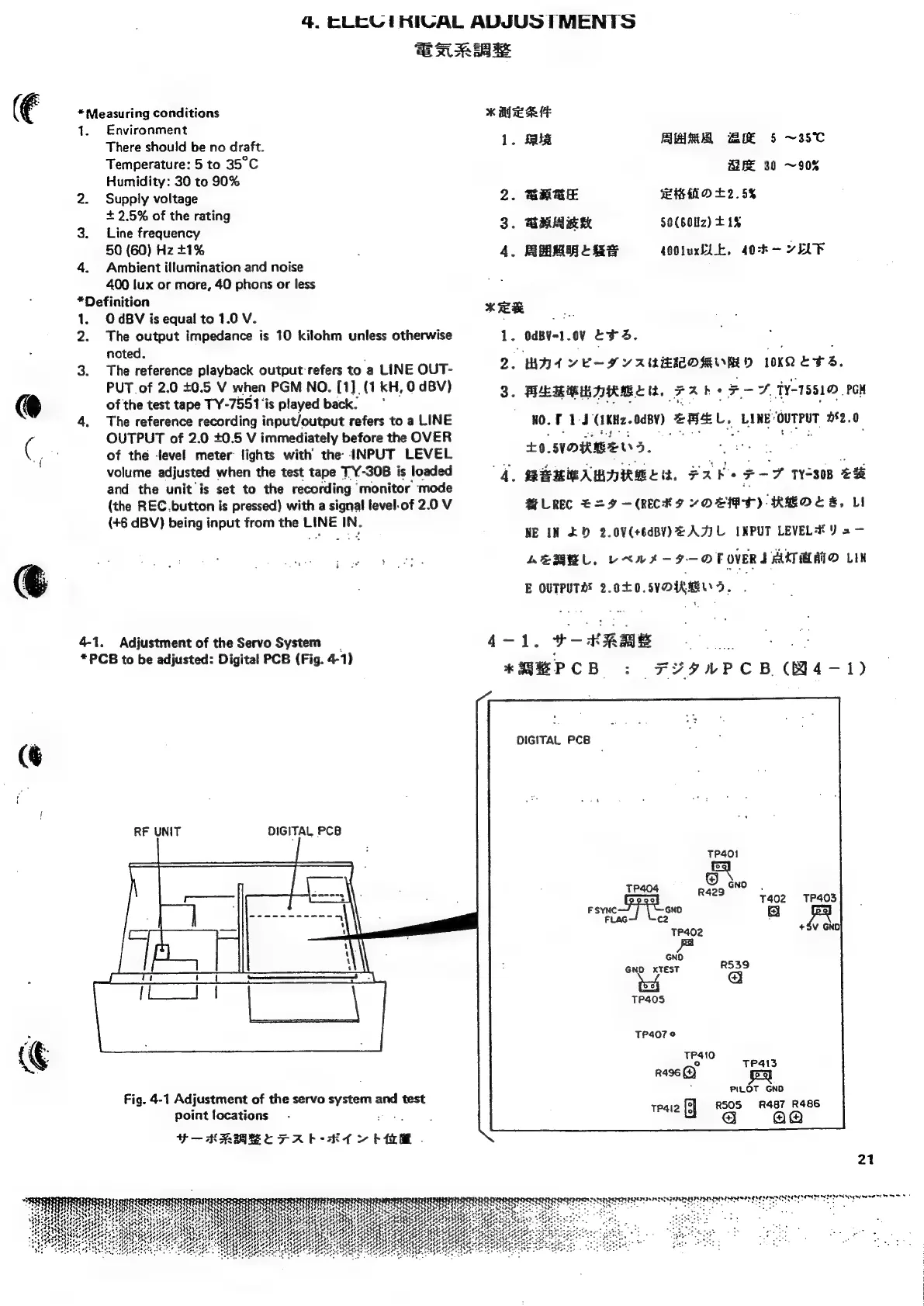
4-1.
Adjustment
of
the
Servo
System
*PCB
to
be
adjusted:
Digital
PCB
(Fig.
4-1)
(@
RF
UNIT
DIGITAL
PCB
Fig.
4-1
Adjustment
of
the
servo
i
and
test
point
locations
—ERABECTFAR
KL
>
bit
.
4.
RRRMRBLRS
400luxELE,
40:k-
~ELF
KER
1.
OdBY~1.0¥
Eva.
2.
waty
YE-S
YAUWEIMORVED
10K
b+.
3.
EMM
DRM
LIL,
72
FAT,
TY-1551
PCN
WO.
F
1(1KH2.
0480)
eREL,
LANES
ouTPUT
162.0
+0.
NORGE
S.
wb
4.
MBMIBAMDRMLE,
2K
Lg
F-7
W508
€#
MH
LREC
=H
—
(RECHT
YORT)
RHOE#,
Li
NE
IN
£D
2.0V(+6dBY)
AAU
INPUT
LEVELE
Y
2
—
AERWL,
UXWA-9—-OFOVERI
AMAA
LIN
E
OUTPUTAE
2.00,.SYDIRKELYS.
4-1.
9B
*RBPCB
:
FYINPCB
(4-1)
DIGITAL
PCB
TP404
©
tno
.
ro
at
T402
TP403
Hel
Leg
R
TP402
+5V
GNO
GND
GNO
XTEST
TP405
TP407°
TP410
°
TP4I13
R496
PILOT
GND
486
TP4i2
a
as
8
21
SRE
ESEME
SAS
LESION
AY
SEEN
aga
oy
a
wees: