EasyManua.ls Logo

Tascam DA-P1 - ATF Level Checks; ATF Play Level Check; ATF Record Level Check and Adjustment

Tascam DA-P1
59 pages
Print Icon
To Next Page IconTo Next Page
To Previous Page IconTo Previous Page
Loading...
3.
=
Checking
the
ATF
Play
Level
1).
Connect
CHI
of
the
oscilloscope
to
TP336(PILOT)
and
CH2
to
TP347(SWH).
2).
Load
a
level
test
tape
(TY-7111
or
TY-7111X)
then
set
the
deck
to
PLAY
mode.
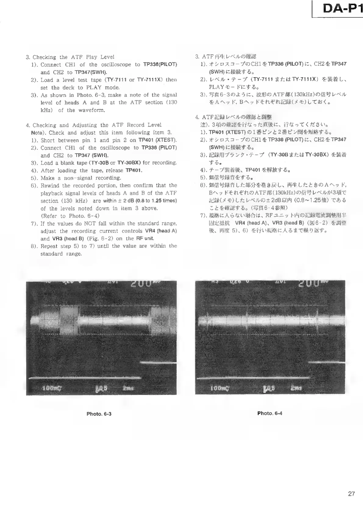
3).
As
shown
in
Photo.
6-3,
make
a
note
of
the
signal
level
of
heads
A
and
B
at
the
ATF
section
(130
kHz)
of
the
waveform.
Checking
and
Adjusting
the
ATF
Record
Level
Note).
Check
and
adjust
this
item
following
item
3.
1).
Short
between
pin
1
and
pin
2
on
TP401
(XTEST).
2).
Connect
CHI
of
the
oscilloscope
to
TP336
(PILOT)
and
CH2
to
TP347
(SWH).
3).
Load
a
blank
tape
(TY-30B
or
TY-30BX)
for
recording.
4).
After
loading
the
tape,
release
TP401.
5).
Make
a
non-signal
recording.
6).
Rewind
the
recorded
portion,
then
confirm
that
the
playback
signal
levels
of
heads
A
and
B
of
the
ATF
section
(130
kHz)
are
within
+
2
dB
(0.8
to
1.25
times)
of
the
levels
noted
down
in
item
3
above.
(Refer
to
Photo.
6-4)
Т).
If
the
values
do
NOT
fall
within
the
standard
range,
adjust
the
recording
current
controls
VR4
(head
A)
and
VR3
(head
В)
(Fig.
6-2)
on
the
RF
unit.
8).
Repeat
step
5)
to
7)
until
the
value
are
within
the
standard
range.
Photo.
6-3
3.
>
DA-P1
ATF
再生
レベ
ル の
確認
1).
オシ
ロス
コー
プ
の
CH1
を
TP336
(PILOT)
に
、
CH2
を
TP347
(SWH)
に
接続
する
。
2).
レベ
ル
・
テ
ー
ブ
(TY-7111
また
は
TY-7111X)
を
装着
し
、
3).
写真
6-3
の
よう
に 、
波
形 の
ATF
部
(130kHz)
の
信号
レベ
ル
を
A
ヘ
ッ
ド
,
B
ヘ
ッ
ド
それ
ぞ
れ
記録
(メモ
)
し
て
お
く
。
ATF
記録
レベ
ル
の
確認
と
調整
注
).
3
項
の
確認
を
行なっ
た
直後
に
、
行
な
っ
て
くだ
さい
。
1).
TP401
(XTEST)
の
1
番
ピ
ン
と
2
番
ピ
ン
間
を
短絡
する
。
2).
オシロスコープ
の
CH1
を
TP336
(PILOT)
に
、
CH2
を
TP347
(SWH)
に
接続
する
。
記録
用
プランク
・
テ
ー
プ
(TY-30B
ま
た
は
TY-30BX)
を
装着
する
。
④.
テー
プ
装
着
後
、TP401
を
解放
する
。
5).
無
信号
録音
を
する
。
6).
無
信号
録音
し
た
部
分
を
巻き
戻し
、
再
生
し
た
と
き
の
A
ヘ
ッ
ド
,
B
ヘ
ッ
ド
それ
ぞ
れ
の
ATF
部
(130kHz)
の
信号
レベ
ル
が
3
項 で
記録
(メモ
)
し
た
レベ
ル
の
ェ
2dB
以
内
(0.8~
て
1.25
倍
)
で
ある
こと
を
確認
する
。(
写
真
6-
4
参照)
.
規格
に
入ら
な い
場
合
は
、RF
ユ
ニッ
ト
内
の
記録
電流
調整
用
半
固定
抵抗
VR4
(head
A)、VR3
(head
B)
(
図
6-2)
を
調整
後
、
再
度
5)、6)
を
行い
規格
に
入る
まで
繰り
返す
。
3).
7.
Photo.
6-4
27