EasyManua.ls Logo

Tascam M-320 User Manual

Tascam M-320
167 pages
To Next Page IconTo Next Page
Page #1 background imageLoading...
Page #1 background image








Table of Contents

Question and Answer IconNeed help?

Do you have a question about the Tascam M-320 and is the answer not in the manual?

Tascam M-320 Specifications

General IconGeneral
Channels20
Bus4
Phantom PowerYes
TypeAnalog Mixer
Outputs4 bus, monitor
EQ3-band (high, mid, low) per channel
Weight16 kg

Summary

TASCAM M-300 Series Mixing Consoles

Operation and Maintenance

Manual section detailing operation and maintenance procedures.

Introduction

TASCAM 300 Series Mixers Overview

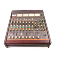
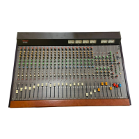
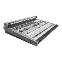
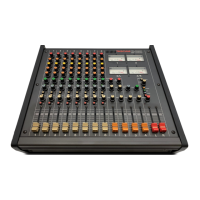
Overview of TASCAM 300 Series mixers and their design for flexibility.

Submix Systems Explained

Explanation of the mixer's subsystem design for various functions.

Systems Introduction

Main Mix System Description

Description of the primary mixing system and its capabilities.

Auxiliary and Effects Submix Systems

Details on AUX and EFFECT submix systems for separate mixing duties.

Effects Return and Monitor Systems

Effects Return System Overview

Description of the effects return subsystem and its function.

Monitor System Operation

Overview of the monitor submix system and its role in multitrack recording.

Features and Functions: Input Channel

Input Channel Controls

Details on the input connectors and controls for each channel strip.

Input Channel Signal Routing and Controls

LINE IN Signal Routes

Explanation of signal flow for LINE IN connectors and associated controls.

Equalizer (EQ) Section Details

Description of the three-band equalizer section and its controls.

AUXiliary 1 & 2 Controls

Details on AUX 1 and AUX 2 controls for cue, effect, and monitor sends.

AUXiliary Signal Selection

AUXiliary LINE and POST Select Switches

Explanation of switches that determine AUX signal source and routing.

Channel Signal Processing Controls

EFFECT Send Control and Channel Assign

Description of EFFECT send control and channel assign switches.

PAN Control Function

Description of the PAN control for stereo placement of signals.

Channel Status and Output Controls

Channel ON, PFL, OL, Direct Out, and Fader

Function of channel ON, PFL, OL, Direct Out, and Channel Fader.

Solo (PFL/AFL) Signal Routes

Meter and Monitor Section Controls

Metering Controls and Indicators

Explanation of VU meters, Peak LEDs, and Meter Select Switches.

Tape Return Signal Routing

Operation of TAPE RTN select switch and AUX send routing.

Monitor Section Controls

Details on Monitor LEVEL, PAN, and ON controls.

Auxiliary and Effects Master Send Controls

MASTER Level Controls

Description of MASTER level controls for AUX and EFFECT systems.

AUX 3 & 4 SUM Switch

Function of the AUX 3 & 4 SUM switch for mono mixing.

Effects Return System

EFFECT RTN and Controls

Description of EFFECT RTN inputs, LEVEL, PAN, and PFL controls.

Stereo and Mono Master Sections

Master Faders and Insert Jacks

Details on stereo/mono faders and insert jacks for master control.

Stereo and Mono Outputs

Output specifications for stereo and mono masters via XLR and RCA.

Monitor Section

Monitor Select Switches and Level Control

Selection and level adjustment for monitor signal sources.

Monitor Outputs and SOLO System

Monitor Outputs and Headphone Controls

Description of monitor outputs, headphone level, and jack.

External Inputs and SOLO System

External inputs and SOLO system for advanced routing and mixing.

Additional Rear Panel Features

SUB IN Jacks

Description of SUB IN jacks for adding external signals to busses.

EXT SOLO and TAPE INs

Features for external solo signals and tape input connections.

Operational Notes and Applications

Basic Sound Reinforcement

Guidance on using the mixer for live sound reinforcement applications.

Basic Connections

Details on making basic audio connections for mixers.

Basic Recording Procedure

Basic Connections for Recording

Connecting the mixer to a four-track recorder for recording.

Recording Studio Signals

Performer's Cue and Monitor System Setup

Setup for performer's cue system, control room monitor, and studio system.

Recording the Basic Tracks

Technique for recording tracks one at a time using PGM busses.

Eight Track Recording and Mixdown

Mixdown Procedure

Steps for mixing down multitrack master tapes to a stereo format.

Video Production and Audio Sweetening

Monitoring Mix Components and Recorder Signals

How the monitor section handles mix components and signal flow to the edit recorder.

Calibrating Mixers for Recording

Connecting Recorder Outputs and Setting Faders

Procedure for connecting recorder outputs and adjusting master faders.

Verifying Meter Readings

Checking meter readings for accuracy during calibration.

How to Use the Equalizer (EQ) Section

EQ Section Description

Description of the three-band semi-parametric EQ section and its controls.

Adjusting EQ Controls

Technique for adjusting frequency and gain controls for desired tonal changes.

A Word of Mixing Advice

Signal Balancing and Fader Relationships

Importance of signal balancing and proper fader relationships for optimal sound.

Accessories for TASCAM Mixers

Microphones, Cables, and Fader Knobs

Descriptions of microphones, insertion cables, and fader link knobs.

Headphone Amplifier and Patch Bays

Information on headphone amplifiers and patch bay systems.

PB-64 and PB-32 Patch Bays

TASCAM PB-32 Series Patch Bays

Description of PB-32 series patch bays for multitrack recording.

M-308 Specifications

Mechanical and Electrical Characteristics

Detailed specifications for the M-308 mixer's physical and electrical properties.

M-308 Performance Characteristics

Performance Characteristics

Specifications for THD, IMD, frequency response, and cross-talk.

M-312 Specifications

Mechanical and Electrical Characteristics

Physical and electrical specifications for the M-312 mixer.

M-312 Performance Characteristics

Performance Characteristics

Performance metrics including equivalent input noise and signal-to-noise ratio for M-312.

M-320 Specifications

Mechanical and Electrical Characteristics

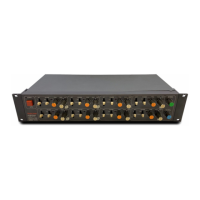
Physical and electrical specifications for the M-320 mixer.

M-320 Performance Characteristics

Performance Characteristics

Performance metrics including THD, IMD, and frequency response for M-320.

Voltage Conversion

Voltage Conversion Procedure and Notes

Steps for changing mixer voltage and important notes.

M-308 Block Diagram

M-312/M-320 Block Diagram

M-308 Level Diagrams

Main Signal Flow (M-308)

Diagram illustrating the primary signal path through the M-308 mixer.

Effect Rtn / Monitor Signal Flow

M-312/M-320 Level Diagrams

Main Signal Flow (M-312/M-320)

Diagram of the main signal flow for M-312/M-320 mixers.

Level Setting and Operation Check

Master Faders and Pots Check

Procedure for checking master faders and pots with signal inputs.

VU Meters and Peak LEDs Check

Verifying VU meter and Peak LED operation during level checks.

Channel and Monitor Signal Checks

Channel Assign Switches and PAN Controls Check

Checking channel assignment and PAN controls for correct output levels.

Monitor Output Signal Verification

Verifying monitor output signals with select switches and level controls.

Effect Return System Check

Effect Return System Check

Checking effect return system levels for stereo outputs.

PGM OUT/TAPE RTN Monitor Systems Check

PGM OUT/TAPE RTN Monitor Systems Check

Checking PGM OUT monitor system and TAPE RTN select switch.

AUX and Talkback System Checks

AUX 3, AUX 4 Outputs and SUM Switch Check

Verifying AUX 3/4 outputs and SUM switch function on M-312/M-320.

Talkback System Check

Testing the talkback system on M-312/M-320 by applying signal and adjusting level.

Performance Measurements

Frequency Response, THD, and S/N Ratio

Measurement procedures for frequency response, THD, and S/N ratio.

Exploded Views, Assemblies, Parts Lists and Circuit Schematics

Instructions for Service Personnel

Important instructions for service personnel regarding safety and measurements.

Notes on Parts and Components

Notes regarding parts marking, resistor/capacitor values, and safety critical components.

3-1. Input PCB Ass'y

3-2. Input Jack PCB Ass'y

3-3. Input Buss A PCB Ass'y

3-4. Input Buss B PCB Ass'y

3-5. Input Buss C PCB Ass'y

3-6. Buss Amp PCB Ass'y

3-7. Buss Jack PCB Ass'y

3-8. Bal Amp L PCB Ass'y

3-9. Bal Amp R PCB Ass'y

3-10. AUX PCB Ass'y

3-11. Mono Amp PCB Ass'y

3-12. Monitor PCB Ass'y

3-13. Mon Buss PCB Ass'y

3-14. Meter PCB Ass'y

3-15. Talkback PCB Ass'y

3-16. Jack A PCB Ass'y

3-17. Jack B PCB Ass'y

3-18. Jack C PCB Ass'y

3-19. Sub In PCB Ass'y

3-20. TB Mic PCB Ass'y

3-21. TR PCB Ass'y (A)

3-22. TR PCB Ass'y (B)

3-23. Power Supply PCB Ass'y

3-24. SW PCB Ass'y

3-25. RIAA PCB Ass'y

Schematic Diagrams

4-1. Wiring Diagram (M-308)

Wiring diagram illustrating connections for the M-308 mixer.

4-2. Wiring Diagram (M-312)

4-3. Wiring Diagram (M-320)

4-4. Input PCB Ass'y

4-5. Buss Amplifier PCB Ass'y (M-308)

4-6. Buss Amplifier PCB Ass'y (M-312/M-320)

4-7. Auxiliary PCB Ass'y (M-308)

4-8. Auxiliary PCB Ass'y (M-312/M-320)

4-9. Balanced Amplifier L PCB Ass'y

4-10. Balanced Amplifier R PCB Ass'y

4-11. Mono Amplifier PCB Ass'y (M-308)

4-12. Mono Amplifier PCB Ass'y (M-312/M-320)

4-13. Monitor PCB Ass'y (M-308)

4-14. Monitor PCB Ass'y (M-312/M-320)

4-15. Meter PCB Ass'y

4-16. Talkback PCB Ass'y (M-312/M-320)

4-17. Power Supply Section (M-308)

4-18. Power Supply Section (M-312/M-320)

4-19. RIAA PCB (M-308) (Japan Model Only)

4-20. IC Internal Block Diagrams

4-20. Block Diagram (M-308)

4-21. Block Diagram (M-312/M-320)

4-22. Level Diagrams (M-308)

4-23. Level Diagrams (M-312/M-320)

Related product manuals