IMPORTANT SAFETY PRECAUTIONS
8 TASCAM US-1641
2 – Features of the US-1641
8 TASCAM US-1641
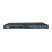
Front Panel
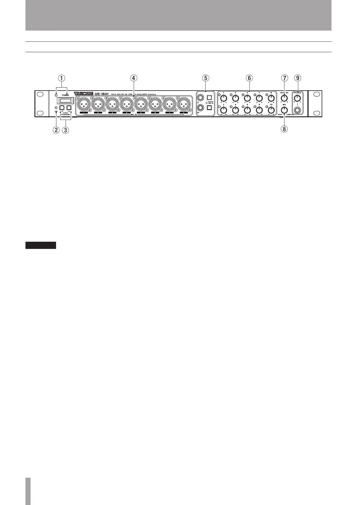
1 POWER switch and indicator Turns the power to
the unit on or off. The POWER indicator lights up red
when the power is on.
2 USB indicator Lights up green to indicate a valid
USB connection to the host computer.
3 PHANTOM [1-4/5-8] switches Turn on the +48V
phantom power supplied to the MIC IN [1-8] jacks.
Each switch turns on the phantom power for four input
channels as a group. The phantom power is on when the
switches are pushed in.
Turn this switch on only if you are using condenser
microphones that require phantom power.
Do not connect or disconnect microphones from the
US-1641 while phantom power is on.
Never supply phantom power to unbalanced
dynamic microphones.
Some ribbon microphones can be damaged by
phantom power. If you are not sure about your
ribbon microphone, do not supply phantom power
to the ribbon microphone.
4 MIC IN [1-8] jacks These are XLR balanced analog
mic input jacks. Use the Gain knobs to adjust the input
gain level.
The wiring is as follows:
pin 1 = ground, pin 2 = hot, pin 3 = cold.
5
LINE IN/GUITAR [9/10] jacks and select switches
These stereo 1/4” phone jacks function as unbalanced
guitar input jacks when the select switches are set to the
GUITAR position, and function as balanced line input
jacks when the switches are set to the LINE IN position.
(The wiring is as follows: sleeve = ground, tip = hot, ring =
cold.) Use the Gain knobs to adjust the input gain level.
6 Gain knobs and indicators [1-10] Adjust the gain
level for Inputs 1-10 individually. The adjustable range
is from –2dBu to –58dBu for Mic Inputs 1-8, and from
+4dBu to +42dBu for Line Inputs 9-10. The Gain indi-
cators will light green when a signal at a certain level
(–30dBFS) or higher is present. However, if the signal level
exceeds –2dBFS, the indicators will light red.
7 MONITOR knob Adjusts the level of signals output
from the MONITOR OUTPUTS [L/R] jacks on the rear
panel.
8 MIX knob Controls the balance of the signal sources
being output from the MONITOR OUTPUTS [L/R] jacks
and the PHONES jack. With this knob turned to the far
left, the US-1641 will output the signal input from the MIC
IN [1-8] jacks and LINE IN [9-14] jacks. With this knob
turned to the far right, the US-1641 will output the signal
received from the computer via USB.
9 PHONES jack and PHONES LEVEL knob This
stereo 1/4" headphone jack outputs the same signal that is
output from the MONITOR OUTPUTS [L/R] jacks. The
PHONES LEVEL knob controls the output level of the
PHONES jack.
2 – Features of the US-1641


 To Next Page