CAUTION
CAUTION
Maximum operating pressure 250 PSI (17 bar). Do not exceed 250 PSI on either side of the valve.
Valve must be properly connected. Mismatched or damaged connectors may cause leaking or
uncoupling under pressure and could cause injury.
CAUTION
The electric Ball Intake Valve RC and the Jumbo Ball Intake Valve RC may be remotely operated.
The electric drives are current limited but may still produce enough force to cause injury. Keep
hands and fingers away from pinch points on the valve.
CAUTION
Do not use the manual override hand wheel while the electric controls are in operation. The electric
drives produce enough torque to cause injury.
CAUTION
The Ball Intake Valve RC and the Jumbo Ball Intake Valve RC have current limiting capabilities
which stops the motor if an obstruction is encountered. The Ball Intake Valve RC and the Jumbo
Ball Intake Valve RC must be installed as instructed using the correct controls and electrical
boxes. Failure to do so will result in damage to the electric motor and loss of current limiting
controls. This may result in injury.
3
©Copyright Task Force Tips, Inc. 2002-2006
The Ball Intake Valve and the Jumbo Ball Intake Valve are intended for use on the intake manifold of a fire engine. An electric remote
controlled (RC) model allows the valve to be operated from a remote location. The valve is kept closed while the water supply from a
hydrant or another pumper to the engine is being established. This prevents the pump from sucking air through the intake manifold and
losing its prime. Once the supply hose is filled and under pressure, and the air has been vented from the hose, the valve may be opened
to connect the pump to the water supply. An adjustable pressure relief valve mounted on the bottom of the valve opens to relieve any
excess pressure that may damage the hose or the pump. The Task Force Tips Ball Inlet Valve has a unique patented half ball, with a
acts much like a gate valve.thermo-plastic rubber seat, and
3.0 GENERAL INFORMATION
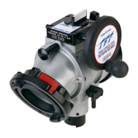
Intake
Elbow
Swivel
Side B
Coupling
Air Vent & Drain
Pressure Relief Valve
Outlet
Side A
Coupling
Handwheel
Shot Pin
Knob
Valve Position Indicator
Air Vent
& Drain
Handwheel
Intake
Elbow
Swivel
Side B
Coupling
AC1ST-NX
Ball Intake Valve
AB1ST-NX
Ball Intake Valve w/Pressure Relief Valve
Shot Pin
Knob
Valve Position Indicator
Outlet
Side A
Coupling
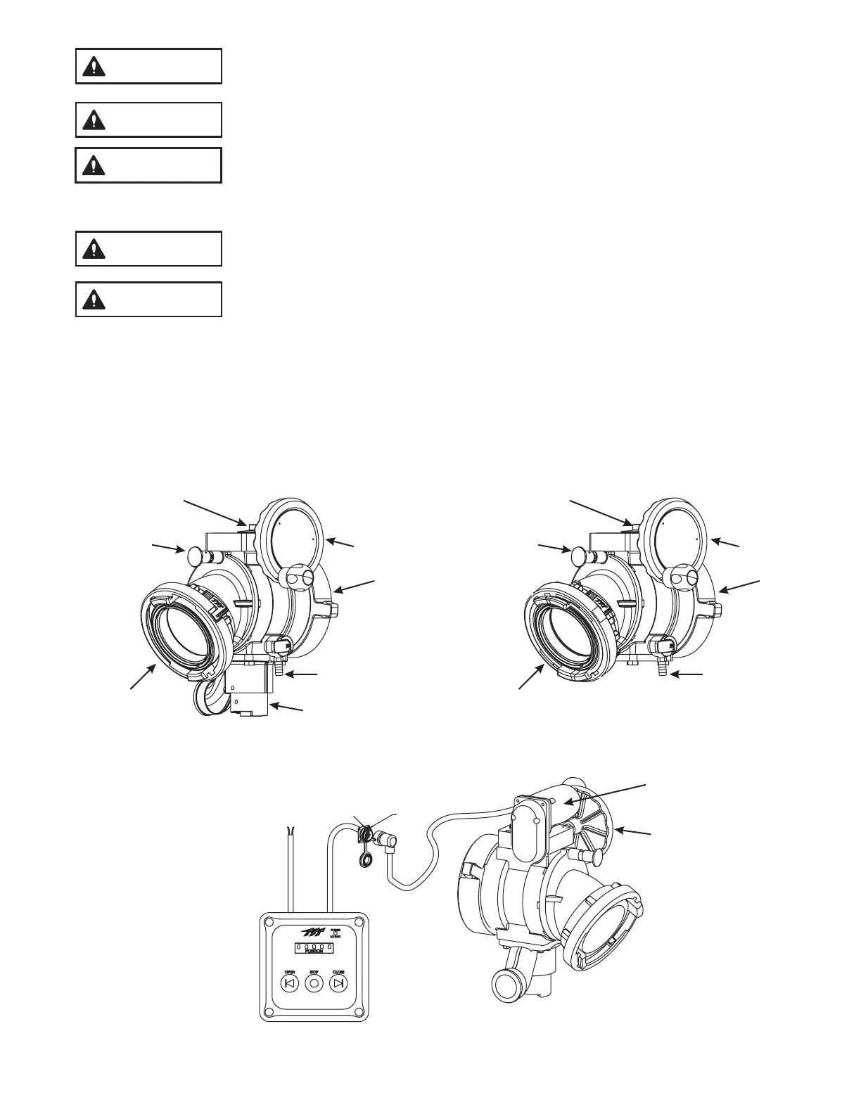
AB1ST-NX-RC
Ball Intake Valve RC and Control Box
Manual Override
Hand Wheel
Electric Motor
PLUG
CONTROLS
HEX NUT
RECEPTACLE
DUST CAP