3
1
2
" (89mm)
3
1
2
" (89mm)
Ø3.75" (95mm)
7/32" (5.5mm) DIA
(4) PLACES
OR TAP FOR
10-32 UNC
THREAD
CUT OUT FOR CONTROLS
Ø1.00" (25mm)
1/8" (3mm) DIA
(4) PLACES
CUT OUT FOR
QUICK CONNECT RECEPTACLE
0.919" (23mm)
OPTIONAL FLAT
INSTALLER CAN USE FLAT OR #4
SCREWS TO STOP ROTATION
0.964" (24.5mm)
SQUARE
2' (610mm)
PLUG
10' (3m)
10' (3m)10' (3m)
CONTROLS
BIV
HEX NUT
RECEPTACLE
DUST CAP
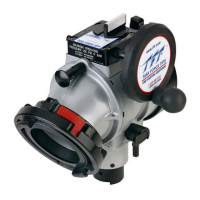
4.0 INSTALLATION
Screw the large coupling to the pump inlet manifold. The valve position indicator should be clearly visible, but need not be level.
4.1 MOUNTING ON TRUCK
Hose couplings are attached using polymer bearing rings which provides electrical insulation to help prevent galvanic corrosion. Task
Force Tips is using a three-step process to fight corrosion. The cast aluminum parts in this valve have been impregnated to fill the
microscopic pores in the cast aluminum. The parts are then hard anodized, and finally powder coated, inside and out, to help prevent
corrosion. The effects of corrosion can be minimized by good maintenance practice. See section 10.0 for maintenance.
3.2 CORROSION
3.3 USE WITH SALT WATER
Use with salt water is permissible provided valve is thoroughly cleaned with fresh water after each use. The service life of the valve
may be shortened due to the effects of corrosion and is not covered under warranty.
3.1 SPECIFICATIONS
MODEL
Waterway Size
Max Pressure
Opening/Closing Speed
Opening/Closing Speed
Voltage
Current Draw
BALL
INTAKE VALVE
3.65” (93mm)
250 psi (17 bar)
BALL INTAKE
VALVE RC
3.65” (93mm)
250psi (17 bar)
6 sec
6 sec
12 or 24volt DC
3 amps running
10 amps current limiting
4.2 ELECTRIC INSTALLATION AND WIRING
4
©Copyright Task Force Tips, Inc. 2002-2006
IMPORTANT!!
NOTE: Override
knob will only turn in one direction.
When mechanical installation and electrical connections are complete, perform the following test to verify voltage supply is adequate
and the current limiting feature is functioning.
1) Apply power to monitor control box.
2) Press OPEN or CLOSE button and hold until monitor reaches its stop position. Continue to hold button down.
3) Once movement is stopped, manually turn override knob in opposite direction while continuing to hold button down. If knob
can be turned, then voltage supply is adequate. If knob cannot be turned and motor continues to operate, then the voltage
supply or wiring is not adequate. Check connections and voltage connection point, rewire if necessary.
WARNING
The electric motor and other components are ignition sources. The electric BIV should be operated
only in areas where there is adequate ventilation and no hazard of flammable vapor buildup.
NOTE:
CABLE IS GEL FILLED TO PREVENT MOISTURE WICKING INTO ENCLOSURE.
GEL IS NON-HAZARDOUS AND SHOULD BE WIPED OFF CONDUCTORS WITH RAG.
See Full Size Templates Section 12, page 15
JUMBO BALL
INTAKE VALVE
5.25” (133mm)
250 psi (17 bar)
JUMBO BALL
INTAKE VALVE RC
5.25” (133mm)
250psi (17 bar)
6 sec
6 sec
12 or 24volt DC
3 amps running
10 amps current limiting
RED(+) AND BLACK (-) TO
POWER DISTRIBUTION CENTER
15 AMPS OVER CURRENT DEVICE