0
25
50
75
100
125
150
175
200
225
250
275
300
0 25 50 75 100 125 150 175 200
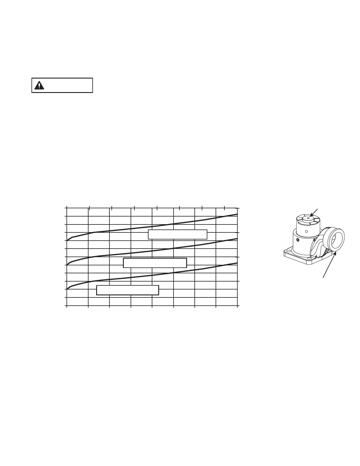
FLOW (GPM)
PRESSURE (PSI)
0
5
10
15
20
0 100 200 300 400 500 600 700
FLOW (LPM)
125 PSI SETTING
200 PSI SETTING
50 PSI SETTING
PRESSURE (BAR)
This valve is equipped with an Air Vent/Drain which will allow the air to escape from the valve when the hose is charged.
TheAir Vent/Drain is opened by turning the knob counter clockwise and closed by turning it clockwise.
To drain the water out of the valve after use open the Air Vent/Drain. A 1/2” diameter plastic tube may be used to run the
drain behind the pump panel.
To set the relief valve pressure turn the adjusting screw on the relief valve housing until the surface of the screw is even
with the desired pressure. Do not cap or plug discharge opening.
6.0 AIR VENT AND WATER DRAIN
7.0 PRESSURE RELIEF VALVE
7.1 RELIEF VALVE SETTING PRESSURE
7.2 RELIEF VALVE FLOW vs. PRESSURE CURVE
If there is a pressure relief valve on the bottom side of the valve. It may be set to any pressure between 50 and 200 p.s.i.. Its
function is to protect the pump and the supply hose from excess pressure. The relief valve may be mounted with its
opening facing the front, back, right or left. A piece of hose or tubing may be mounted on the round spout to direct the water
coming out of the relief valve away from the pump panel. To change the orientation of the relief valve, remove the four 7/16
bolts on the corners of the relief valve flange, orient the valve the way you want it, and replace the bolts. Use a drop of
thread locking compound on the threads of the bolt to prevent them from coming loose.
PRESSURE RELIEF VALVE PERFORMANCE
Adjusting
Screw
Relief Valve
Discharge Opening
CAUTION
Loss of prime can interrupt water flow and cause injury or death. Always bleed
out air with air valve to prevent possible loss of prime.
7
©Copyright Task Force Tips, Inc. 2002-2006