4.3 CHANGING HAND WHEEL TO LEFT SIDE (NON RC MODELS)
The handwheel is shipped from the factory on the right
hand side of the valve. The hand wheel. can be switched to
the left hand side for convenience or if it interferes with
other equipment on the pump panel.
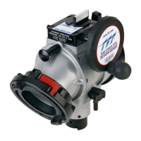
To move the hand wheel to the opposite side, remove the retaining ring on the end of
the shaft. Pull the shaft out of the gear box.As the shaft is withdrawn, grasp the small
key on the shaft so it does not get lost. Remove and switch the two plastic bushings
that come out of the sides of the gearbox. The bushing with the large hole is installed
on the same side as the handwheel. Look through the gear box and note
approximate position of the keyway in the worm inside the gear box. Slide the shaft
into the gearbox on the opposite side of the gear box with the key oriented the same
as the keyway. A small dab of grease will keep the key place. Rotate the shaft until
the key finds the keyway and push the shaft in until it stops. Reinstall the retaining
ring. Do not over expand the retaining ring.
RETAINING
RING
KEY
SHAFT ASSEMBLY
LARGE
BUSHING
SMALL
BUSHING
5
©Copyright Task Force Tips, Inc. 2002-2006
4.4 CHANGING HAND WHEEL TO LEFT SIDE (RC MODELS)
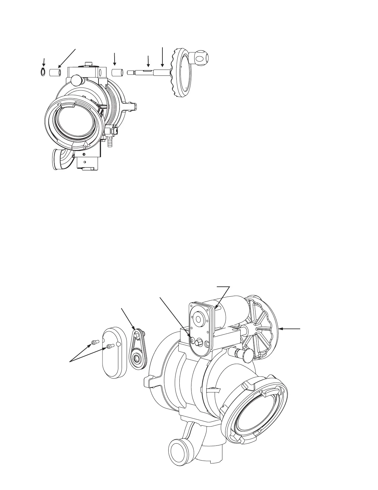
STEP 1: Remove screws and end cover
STEP 2: Slide off both sprockets and chain as one unit.
STEP 3: Remove button head screw and lock washer to remove motor unit.
STEP 4: Remove 4 screws and reposition motor so electric wire points in desired direction.
STEP 5: Change hand wheel to other side as in Section 4.3.
STEP 6: Reverse steps 1, 2 and 3 to reinstall motor on other side.
STEP 7: Reverse polarity of motor by holding OPEN and CLOSE buttons together for 15 seconds.
NOTE: Remove set screw that is in hole for the button head screw and reinstall the set screw on the other side.
The set screw plugs the hole to keep dirt from entering the gearbox.
STEP 1
STEP 2
STEP 3
STEP 4
STEP 5