11
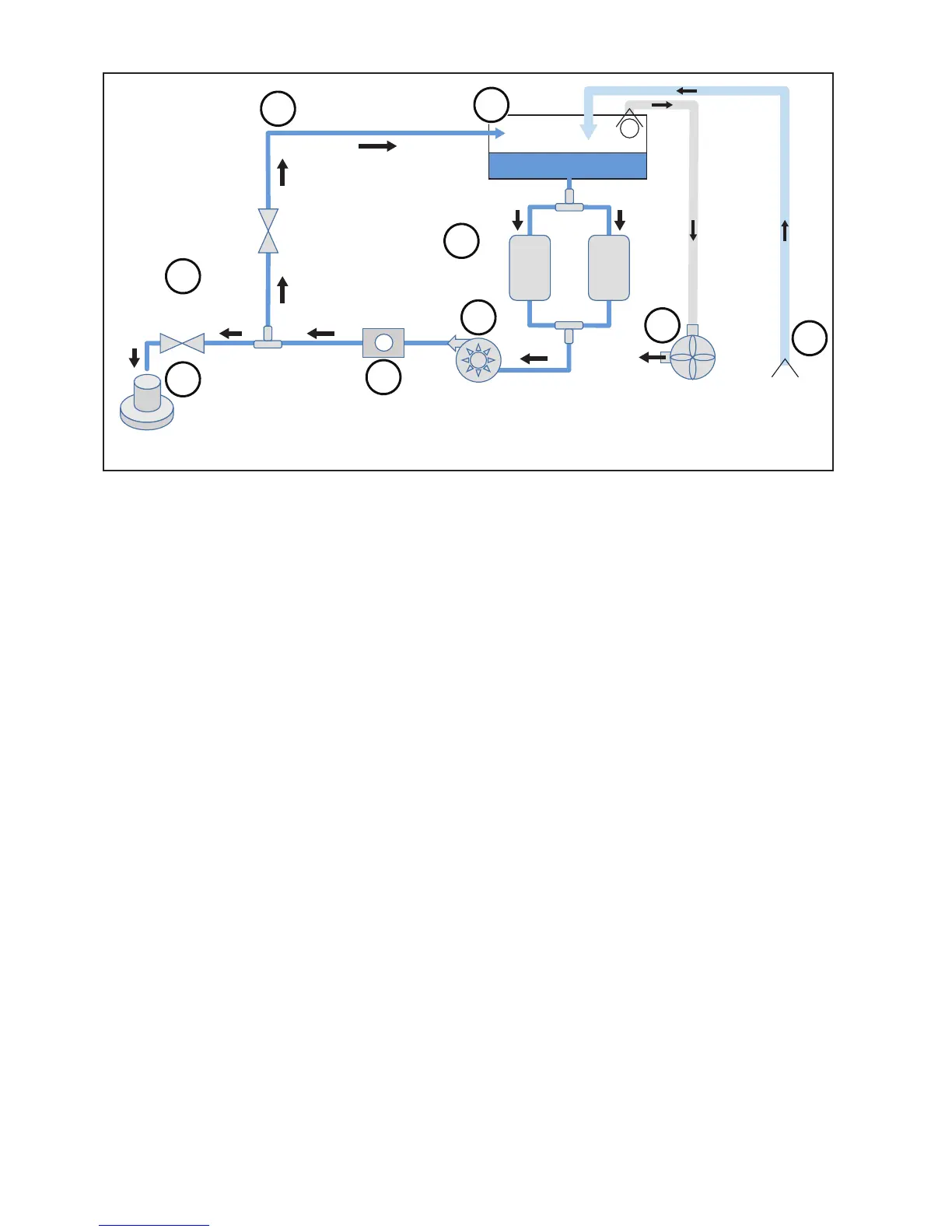
12.1. TASKI Intellibot SWINGOBOT 1650 CE Flow Diagram (Parallel)
10
um
10
um
BYPASS
VALVE
WATER
VALVE
TANK
FLOW
SENSOR
FILTRATION
VACUUM SQUEEGEE
F
CYLINDER
SCRUB
CIRCULATION
PUMP
1
7
4
3
2
8
9
6
5
Figure: 18
1 The robotic oor scrubber system utilizes 53-liter tank for storing and recycling cleaning solution.
2 The standard system uses a parallel canister ltration system with two 10 micron lters. Optional lters are
also available.
3 The circulation pump provides ow for the cleaning solution.
4 A ow sensor is used to detect and set an appropriate ow rate for effective scrubbing.
5 Water valves provide ow regulation for wash water or recycling of the cleaning solution.
6 Cleaning solution is distributed directly onto the scrubbing head.
7 When not scrubbing, the cleaning solution is recycled back to the tank and continually ltered.
8 A vacuum system evacuates air from the top of the tank, providing suction for the vacuum squeegee
9 The squeegee system wipes used cleaning solution from the oor and the pickup tube directs the used
solution back to the tank.