12
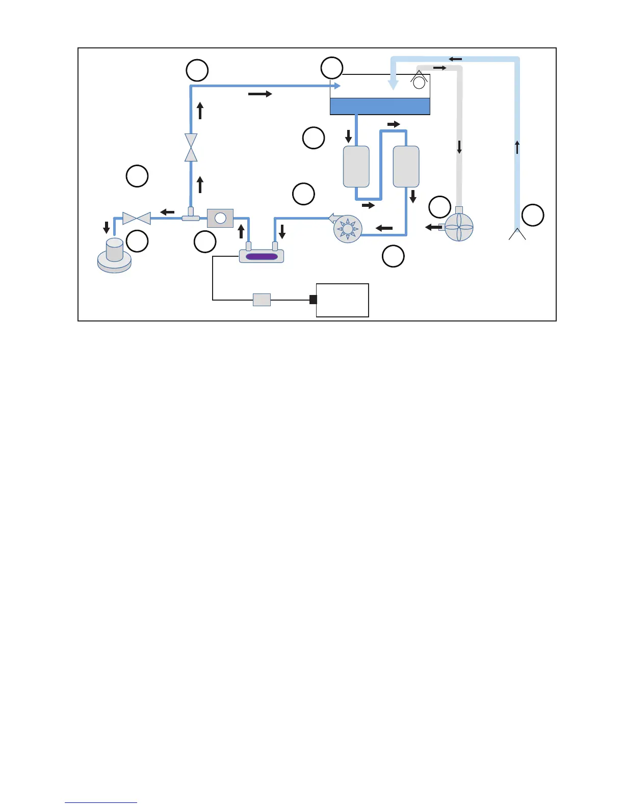
12.2. TASKI Intellibot SWINGOBOT 1650 CE UV Flow Diagram (In Series Healthcare Only)
BYPASS
VALVE
WATER
VALVE
TANK
SERIES
FILTRATION
VACUUM SQUEEGEE
SCRUBBER
FLOW
SENSOR
CIRCULATION
PUMP
REACTOR
1
um
10
um
F
BALLAST
DC-TO-AC
INVERTER
UV POWER SUPPLY
1
8
5
3
2
9
10
7
6
4
UV
STERALIZER
Figure: 19
1 The robotic oor scrubber system utilizes 53-liter tank for storing and recycling cleaning solution.
2 The UV ltration system utilizes a 10 micron pre-lter and a 1 micron primary lter to eliminate turbidity for
effective UV penetration into the cleaning solution.
3 The circulation pump provides ow for the cleaning solution.
4 The UV sterilization system includes a power supply, UV ballast, UV lamp, and sterilization reactor to
eliminate microorganisms from the recycled cleaning solution.
5 A ow sensor is used to detect and set an appropriate ow rate for effective scrubbing.
6 Water valves provide ow regulation for wash water or recycling of the cleaning solution.
7 Cleaning solution is distributed directly onto the scrubbing head.
8 When not scrubbing, the cleaning solution is recycled back to the tank and continually ltered.
9 A vacuum system evacuates air from the top of the tank, providing suction for the vacuum squeegee
10 The squeegee system wipes used cleaning solution from the oor and the pickup tube directs the used
solution back to the tank.