17
1. DESCRIPTION
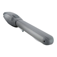
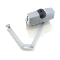
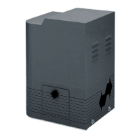
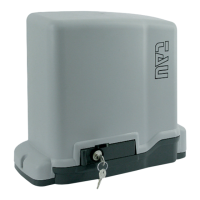
The ARM2000 swing gate operator is an electro-mechanical, irreversible operator that transmits motion to the leaf via a worm screw system.
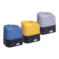
The operator is available in 18V DC and 230V AC versions. All versions are supplied with adjustable closign mechanical stopper.
The irreversible operation ensures the leaf is mechanically locked when the motor is not operating, but it is not intended as a high degree security
deterrent against intrusion attempts and/or tampering. A convenient and safe release system with customised key makes it possible to manually
move the leaf in the event of a malfunction or of a power failure.
ATTENTION:
The correct operation and the declared specications only apply if TAU accessories and safety devices are used.
In the absence of a mechanical clutch, the use of a control unit with an adjustable electronic clutch, or the installation of a
sensitive edge, is required in order to ensure crush-proof safety.
The ARM2000 swing gate operator has been designed and built for controlling vehicle access. It is not intended as a high de-
gree security deterrent against intrusion attempts and/or tampering. Avoid any other use whatever.
ACTUATOR PARTS (g.1)
Nr. Description Nr. Description
1 Operator 6 Terminal board cover
2 Release device 7 Close mechanical stop
3 Worm screw cover 8 Cap
4 Wing connection bracket 9 Open limit switch
5 Rear bracket 10 Close limit switch
2. DIMENSIONS (g.2)
3. INSTALLATION (g.3)
Electrical set-up (standard system - ARM2000IS/IF/IFC) Electrical set-up (standard system
- ARM2000
BI and BR
)
Pos. Description Cables Pos. Description Cables
1 Operator 4x1,5 mm² 1 Operator 2x2,5 mm² + 3x0,5 mm²
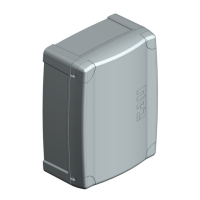
2 Control unit
3x1,5 mm²
(power supply)
2 Control unit
3x1,5 mm²
(power supply)
3 Control unit support - 3 Control unit support -
4 TX photocells 4x0,5 mm² 4 TX photocells 4x0,5 mm²
5 RX photocells 2x0,5 mm² 5 RX photocells 2x0,5 mm²
6 Key switch 3x0,5 mm² 6 Key switch 3x0,5 mm²
7 Flashing light and aerial 2x1 mm² + 1RG58 7 Flashing light and aerial 2x1 mm² + 1RG58
8 Mechanical stopper - 8 Mechanical stopper -
Notes:
• Use suitable tubes and/or hoses to lay electric cables.
• Choose short routes for cables and keep power cables separate from control cables.
Preliminary checks
Prior to installing the operator, make all structural modications in order to ensure safety distances and protect and segregate areas in which
people may be exposed to the risk of crushing, shearing, dragging or similar dangers.
•
Make sure the existing structure is suciently sturdy and stable;
• the mechanical parts must conform to the provisions of Standards EN 12604 and EN 12605;
• leaf length in compliance with the actuator specications;
• regular and uniform movement of the leaves, without any friction and dragging during their entire travel;
• sti hinges in good conditions;
• presence of both opening and closing mechanical limit stops;
• presence of an ecient earthing for electrical connection of the actuator.
Perform any necessary metalwork job before installing the operator.
The condition of the gate structure directly aects the reliability and safety of the gate operator.
Installation dimensions (g.4)
Determine the tting position of the operator with reference to pic. 4.
Make sure space between the open leaf and any obstacles (walls, fences etc.) allows the operator to t.
ENGLISH
 Loading...