19
ENGLISH
4. OPTIONAL ACCESSORIES
P-650ARMKITFCR - Set of mechanical stoppers, containing:
nr. 2 mechanical stoppers; nr. 4 M5x20 screws.
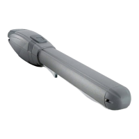
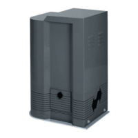
5. WIRING THE ACTUATOR
A terminal board is located in the rear part of the operator for the connection of the motor, of any limit switch and for the grounding of the
operator (pic.14-15).
Connect the motor and the grounding as per pic.14-15 and the table.
ARM2000IS - 230V AC ARM2000IF - 230V AC
POS. COLOR DESCRIPTION POS. COLOR DESCRIPTION
1 Blue
Common
1 Blue
Common
2 Black Phase 1 2 Black Phase 1
3 Brown Phase 2 3 Black OLS
T Yellow / Green Grounding 4 Brown + Red Phase 2 + OLS
T Yellow / Green Grounding
ARM2000IFC - 230V AC Use control units with torque limiting device only.
POS. COLOR DESCRIPTION ARM2000BI - ARM2000BR - 18/24V DC
1 Blue
Common
POS. COLOR DESCRIPTION
2 Black CLS 1 Brown Encoder positive
3 Black OLS 2 Blue Encoder negative
4 Brown + Red Phase 2 + CLS 3 White
Encoder signal
5 Black + Red Phase 1 + OLS 4 Blue Motor negative
T Yellow / Green Grounding 5 Red Motor positive
Use only control units with electric clutch.
The distance between the control unit and the motor must not exceed 10 – 12 m.
TAU srl recommends its composite cable, Code M-03000CC101;
Place the control unit (external versions) in the immediate vicinity of the motors.
Be careful not to run cables for auxiliary devices inside raceways housing other cables supplying power to large loads or lights
with electronic starters.
In the event control pushbuttons or indicator lights are installed inside homes or oces several metres away from the actual
control unit, it is advisable to decouple the signal by means of a relay in order to avoid induced interference.
6. START-UP
ATTENTION: Cut power before any job on the operator or the controller.
Carefully observe points 10, 11, 12, 13 and 14 of the SAFETY GENERAL RULES.
With reference to the indications in pic. 3 and in the table (see INSTALLATION), set the ducts and carry out the electrical connections of the
control board and of the chosen accessories.
Choose short routes for cables and keep power cables separate from control cables.
1) Power the system and check the status of the LEDs according to the control unit instructions.
2) Program the control board according to the needs by following the given instructions.
7. TESTING THE AUTOMATED SYSTEM
• Carefully check operating eciency of the gate operator and of all accessories connected to it, paying special attention to the safety devices.
• Hand the “User Guide” to the end user together with the Maintenance register.
• Explain correct operation and use of the gate operator to the end user.
• Indicate the potentially dangerous areas of the gate operator to the end user.
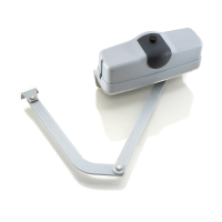
8. MANUAL RELEASE
If the gate operator needs to be moved manually due to a power failure or to an actual malfunction, proceed as follows:
1_ Cut power by means of the safety circuit breaker (even in the event of a power failure).
2_ Slide the protective cap, pic. 16;
3_ Insert the key and turn it 90°, pic. 17.
4_ As shown in pic.18, rotate the release lever upward in order to release the actuator.
5_ Open or close the leaf manually.
Note: To keep the gate operator in manual operation the release device must be left in its current position and power must
be disconnected.
9. RESTORING NORMAL OPERATION
To reengage the gate operator, proceed as follows:
 Loading...