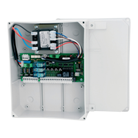
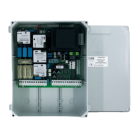
The D750M is a control unit designed for electromechanical gear motors used in automating gates and doors. It is intended for use by qualified technical personnel for installation and maintenance, not for end-users. The unit operates on a single-phase 230 Vac, 50Hz power supply and can control two single-phase motors, each with a maximum nominal power of 300 W. The total maximum nominal power for motors is 600 W.
Function Description
The D750M control unit features microprocessor-controlled logic and includes several integrated functions for enhanced safety and convenience. It incorporates a built-in electronic torque limiting device, which helps prevent damage to the motors and the gate system by regulating the thrust force. The unit also includes electronic control for safety devices, specifically an external photocell control system. This system checks the proper functioning of the photocell relay by cycling its power. If the relay does not switch correctly, the control unit will block for safety reasons. This safety system verification can be disabled by setting dip-switch 6 to OFF, which is recommended only when photocells are not in use.
The D750M supports a pedestrian entry function, allowing partial opening of the gate. It has a built-in flashing light circuit (230 Vac, max 50W) that provides a modulated signal for direct use, with a slightly increased flashing frequency during the closing phase. A gate open warning light (24 Vac, max 3W) is also included, which flashes with the same frequency as the main flashing light during the entire opening and closing maneuver, remains on when the gate is open, and turns off when the gate is closed.
An integrated 433.92 MHz 2-channel radio receiver is a key feature, capable of learning up to 30 radio control codes (dip-switch or rolling code types). The first channel directly controls the gate's open/close function, while the second channel controls a relay for a normally open (N.O.) no-voltage output contact (terminals 21 and 22, max. 24 Vac, 1 A).
The unit also features a "slow-down" function during both opening and closing phases, which can be enabled and adjusted via the RALL trimmer. This deceleration function helps ensure smooth and controlled gate movement.
Important Technical Specifications
- Power Input: 230 Vac - 50Hz
- Max Motors Nominal Power: 600 W ca.
- Primary Input Line Rapid Fuse (F1 - 5x20): F 6.3 A
- Input Voltage of Motor Circuits: 230 Vac
- Input Voltage of Auxiliary Circuits: 24 Vac
- 24Vac Line Rapid Fuse (F2 - 5x20): F 1.6 A
- Logic Circuit Input Voltage: 5 Vdc
- Working Temperature: -20°C ÷ + 70 °C
- Box Protected to: IP43
- Electric Lock Power Output: 12 Vac max. 15 W
- Flashing Light Output: 230 Vac max. 50W
- Gate Open Warning Light Output: 24 Vac max. 3W
- Photocell Transmitter Power Supply: 24 Vac (max. 2 transmitters)
- Radio Receiver: 433.92 MHz, 2 channels, up to 30 codes
Usage Features
The D750M offers several adjustable parameters via trimmers and dip-switches to customize gate operation:
- Trimmers:
- R. ANTA: Second motor delay adjustment.
- T. LAV.: Work time adjustment (determines the "high speed travel" duration).
- CH. AUTO: Automatic closing time adjustment.
- RALLENT.: Deceleration time adjustment.
- Trimmers are adjusted clockwise to increase values and anticlockwise to decrease them.
- Dip-switches:
- Dip 1 (Automatic Closing): ON for automatic closing after a set time (T.C.A. trimmer); OFF for manual closing.
- Dip 2 (Command Sequence): ON for OPEN-CLOSE-OPEN-CLOSE sequence; OFF for OPEN-STOP-CLOSE-STOP-OPEN-STOP (step-by-step) sequence.
- Dip 3 (No Reverse): ON for ignoring close commands during opening; OFF for behavior according to Dip 2.
- Dip 4 (Deceleration): ON to enable and adjust deceleration via RALL trimmer; OFF to disable deceleration.
- Dip 5 (Pre-flashing): ON to enable pre-flashing; OFF to disable it.
- Dip 6 (Photocell Test): ON to enable photocell test; OFF to disable it (use when photocells are not used).
- Dip 7 & 8 (2nd Radio Channel Output Mode): Configures the 2nd radio channel output as "Gate contact open," "Bistable function active," "Monostable function active 2 sec.," or "Monostable function active 180 sec."
- Dip 9 (Ram Blow/Opening Delay): ON to enable "ram blow" for electric lock release (only with electric lock) and, for software versions 3.02 and later, increases the second motor opening delay by 3 seconds; OFF to disable.
- Dip 10 (Sensitive Edge Type): ON for 8.2 KΩ resistive sensitive edge; OFF for fixed sensitive edge.
Maintenance Features
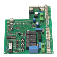
The D750M includes diagnostic LEDs to assist with troubleshooting:
- DL1 (Red): OPEN/CLOSE button signal.
- DL2 (Red): PEDESTRIAN button signal.
- DL3 (Green): STOP button signal.
- DL4 (Green): SENSITIVE EDGE signal.
- DL5 (Green): INTERNAL PHOTOCELL signal.
- DL6 (Green): EXTERNAL PHOTOCELL signal.
- DL7 (Red): RADIO CONTROLS programming signal. This LED also indicates errors with predefined flashes (steady light for normal operation, 2 flashes for phototest error).
For proper operation, any unused Normally Closed (N.C.) contacts must be short-circuited. The system's earthing must comply with current safety regulations. The manufacturer declines responsibility for damages resulting from non-compliance with these instructions. It is crucial to use appropriate cable cross-sections (at least 1.5 mm² for power, motors, earth, and flashing light; 0.5 mm² for control and auxiliary devices) and to keep power circuits separate from control and auxiliary circuits, especially for long runs. The control unit should be installed vertically in a dry and protected place, as close as possible to the gear motor.
Radio Control Programming and Cancellation
- Learning: Press P1 briefly to associate a remote control with the OPEN/CLOSE function. DL7 turns off, then on again upon successful memorization. Up to 30 transmitters can be stored. For the 2nd channel, use P2.
- Remote Programming (Rolling Code): New rolling code transmitters can be programmed remotely using an already programmed transmitter, without direct access to the receiver's programming button.
- Cancellation: Press and hold P1 for 3 seconds to clear all associated remote controls. DL7 flashes slowly, then turns off and back on to confirm cancellation. Repeat with P2 for the second channel. To memorize a new type of remote control (e.g., switching from dip-switch to rolling code), both channels must be cleared.
Troubleshooting
Common issues and solutions include:
- Automation not starting: Check 230Vac power supply, verify N.C. contacts (4 green LEDs on), set dip 6 to OFF (if photocells are not used), and check fuses.
- Poor radio control range: Check antenna connections (ground and signal), avoid extending antenna cable with joints, ensure antenna is not installed in low or hidden positions, and check remote control batteries.
- Gate opening in the wrong direction: Invert motor connections on the terminal block (terminals 5 and 7 for motor 1; terminals 8 and 10 for motor 2).