16
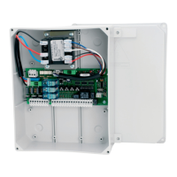
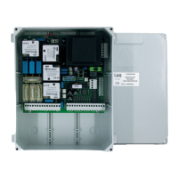
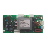
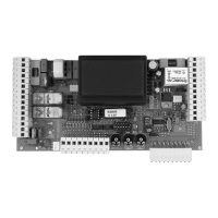
D750M
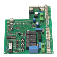
CONTROL CARD FOR TWO SINGLE-PHASE MOTORS 230 Vac
The D750M panel features an electronic photocell control system which switches the external
photocell transmitter on and off thereby causing the control unit microprocessor to check wheth-
er the relay switches correctly. If this does not happen, the control unit is automatically blocked
• MICROPROCESSOR-CONTROLLED LOGIC
• SELF-DIAGNOSIS LED’s
• LINE INPUT FUSE
• BUILT-IN TORQUE LIMITING DEVICE
• ELECTRONIC CONTROL OF SAFETY DEVICES
• PEDESTRIAN ENTRY FUNCTION
• BUILT-IN FLASHING LIGHT CIRCUIT
• 433.92 MHz 2 CHANNEL BUILT-IN RADIO RECEIVER (CH)
• “SLOW-DOWN” FUNCTION IN OPENING AND IN CLOSING PHASE
TESTING
When all connections have been made:
All the green LS LED’s must be on (each corresponds to a Normally Closed input).
They only turn off when the commands they are associated with are active.
All the red LS LED’s must be off (each corresponds to a Normally Open input) they only turn
on when the commands they are associated with are active.
TECHNICAL CHARACTERISTICS
Power input to board 230Vac - 50Hz
Max motors nominal power 600 W ca.
Primary input line rapid fuse (F1 - 5x20) F 6,3 A
Input voltage of motor circuits 230 Vac
Input voltage of auxiliary circuits 24 Vac
24Vac line rapid fuse (F2 - 5x20) F 1,6 A
Logic circuit input voltage 5 Vdc
Working temperature -20°C ÷ + 70 °C
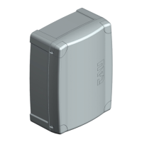
Box protected to IP43
DIAGNOSTICS LED
DL1 OPEN/CLOSE button red LED signal
DL2 PEDESTRIAN button red LED signal
DL3 STOP button green LED signal
DL4 SENSITIVE EDGE green LED signal
DL5 INTERNAL PHOTOCELL green LED signal
DL6 EXTERNAL PHOTOCELL green LED signal
DL7 RADIO CONTROLS programming red LED signal
English
 Loading...