Do you have a question about the tau K125M and is the answer not in the manual?
Details electrical specifications, fuses, operating temperature, and protection ratings.
Input for resistive or fixed safety edge, works on opening.
Input for safety devices active during closure (NC contact).
Output (18 Vdc) for motor supply, max 50W.
Step-by-step guide to program travel limits and automation settings.
Covers RALL (Deceleration), FR (Obstacle Detection), TCA (Auto Closing Time) trimmer adjustments.
Details functions controlled by dip switches 1-10 for logic configuration.
Lists common malfunctions, their causes, and recommended solutions.
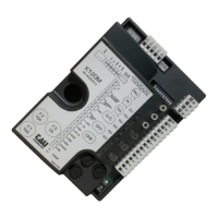
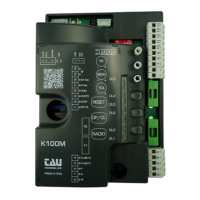
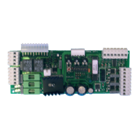
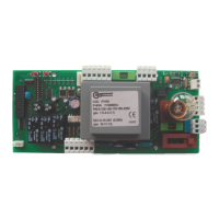
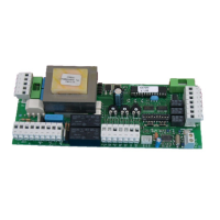
Visual representation of terminal connections and component layout.
| Brand | tau |
|---|---|
| Model | K125M |
| Category | Control Panel |
| Language | English |