Do you have a question about the tau K120M and is the answer not in the manual?
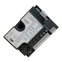
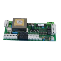
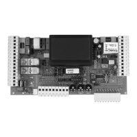
Identifies the K120M control panel for T-ONE3B gearmotors.
Visual representation of K120M terminal connections and component labels.
Details wiring for antenna, 2nd radio channel, and photocell connections.
Statement of product purpose and compliance with EEC directives.
Covers manual scope, proper product use, and installer qualifications.
Details expert installation, risk analysis, and adherence to safety regulations.
Lists electrical and physical specifications of the K120M control board.
Explains the meaning of status and error signals from diagnostic LEDs.
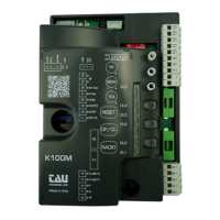
Details connections for power, safety edge, stop, and open/close inputs.
Details connections for photocells, flashing light, warning light, and radio.
Describes connections for radio receiver, encoder, motor, and battery.
Guides on programming travel limits and adjusting logic settings.
Explains the function and configuration options for each dip switch.
Details error codes indicated by the DL3 diagnostic LED for troubleshooting.
Covers obstacle detection sensitivity and slow-down distance adjustments.
Explains gate realignment and the advanced clock function.
Guides on learning, remote programming, and cancelling radio control codes.
Solutions for automation not starting and poor radio control range.
Instructions for inverting motor connections if the gate moves incorrectly.
Details warranty terms, duration, and exclusion cases in various languages.
Fields for retailer/installer stamps and purchase/installation dates.
Fields for end-user name, address, and contact information.
Guidance on attaching product labels or serial numbers for warranty.
| Display | 12.1" TFT LCD |
|---|---|
| Resolution | 1024 x 768 pixels |
| Connectivity | Ethernet, USB, Serial (RS232/RS485) |
| Power Supply | 24V DC |
| IP Rating | IP65 front panel |