Do you have a question about the tau K101M and is the answer not in the manual?
Product installation and servicing must be performed by qualified professionals only.
Using the control unit for purposes other than intended is prohibited by law.
Ensure the gate is correctly installed and moves freely before proceeding with operator installation.
The automatic barrier must be grounded, adhering to all safety codes.
Use only multi-threaded wire and avoid reusing pre-existing electric wires.
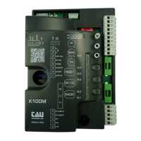
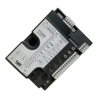
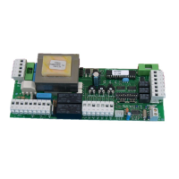
Lists key features including microprocessor logic, status LEDs, radio receiver, soft-stop, and app compatibility.
For long cable runs (>20m), use relays or a 750T-RELE device to prevent malfunctions.
Green LEDs indicate Normally Closed inputs are active when ON.
Red LEDs indicate Normally Open inputs; they turn ON when activated.
Specifies the control board power input as 230V AC, 50-60 Hz.
Details the input fuse rating for 230V AC power supply (F1 - 5x20, F 3.15 A).
States power input for motors (230V AC) and auxiliary circuits (24V AC).
Specifies the operating temperature range and protection degree.
DL1 indicates transmitter programming or error messages.
DL2 indicates the activation of the OPEN/CLOSE pushbutton.
DL3 indicates when the photocell is activated.
DL4 indicates deceleration during the closing maneuver.
DL5 indicates deceleration during the opening maneuver.
DL6 indicates when the STOP pushbutton is activated.
Terminals 1 and 2 are for 230/115V AC power supply (Neutral and Phase).
Terminals 3 and 4 are for 230/115V AC flashing light output (max. 50W).
Terminals 5 and 6 are for 12V DC flashing light output.
Terminals 7-10 for OPEN/CLOSE (NO) and 8-10 for STOP (NC) inputs.
Terminals 9-10 are for photocell/safety devices (NC contact).
Terminals 11-12 supply 24V AC for photocells/receivers (up to 3 pairs).
Terminals 13-14 are for the 433.92 MHz aerial input (Earth and Signal).
M2 terminal for connecting micro switches (Normally Closed contacts).
FS1 and FS2 terminals are for the motor start-up capacitor.
M3 terminal for connecting the 230V AC single-phase motor.
J4 terminal for connecting T-WIFI / T-CONNECT devices for app operation.
SM slot for Memory Card connection for transmitter codes.
Adjusts motor torque, limit switch sensitivity, and automatic closing time.
Adjust limit switch cams to set deceleration points for opening and closing maneuvers.
Configures operational modes like automatic closing, stroke type, and direction.
Sets working times and adjusts SENS trimmer for stroke setup.
DL1 indicates normal operation (steady) or frequency detection errors (slow flashing).
8 flashes on DL1 indicate no motor signal. Check wiring and motor.
Multiple errors are indicated by a 2-second pause between messages.
A timer can keep the automation open at specific times, reverting to auto-closing later.
Channels control opening, a relay output, and pedestrian opening.
Procedure to associate radio controls with the OPEN/CLOSE function via CH1.
Procedure to associate radio controls with the 2nd channel using CH2.
Procedure to associate radio controls with the 3rd channel using CH1 and CH2 simultaneously.
Enables remote self-learning of specific transmitter versions (V 4.X) without physical button presses.
Procedure to cancel all radio control devices associated with CH1, CH2, or CH3.
Control unit memory can be expanded from 30 to 1022 codes using memory cards.
Standard units have 30-code memory; expansion cards are ordered separately.
Procedure to perform a radio memory reset using CH1 and PROG keys.
Connect T-WIFI/T-CONNECT devices to J4 for app operation; refer to app instructions for activation.
Troubleshooting steps for when the operator does not run, checking power, LEDs, and fuses.
Troubleshooting for poor radio control range, checking aerial connections and battery status.
Corrects incorrect opening direction by inverting DIP 4 setting.
| Brand | tau |
|---|---|
| Model | K101M |
| Category | Control Panel |
| Resolution | 1280 x 800 |
| Display | 10.1-inch |
| Processor | Quad-core |
| Operating System | Android |
| Connectivity | Wi-Fi, Bluetooth |
| Protection Rating | IP65 |