7
WARNING!
Attention: This product may only be installed from professional installers. Only qualied and trained electricians may connect,
programme and service the controls.
No information given in this manual can be considered as being of interest to end users.
This manual is enclosed with control unit K101M and may therefore not be used for dierent products!
Important information: Disconnect electric power to the system before making maintenance, repairs or removing covers
The K101M control unit has been designed to control an automatic barrier.
Any other use is considered improper and is consequently forbidden by current laws.
Read all instructions carefully and completely before attempting to install and use this automatic gate operator!
1. INSTALLATION
Make sure the gate has been properly installed and slides freely in both directions. Repair or replace all worn or damaged gate hardware
prior to installation. A freely moving gate will require less force to operate and will enhance the performance of the operator and safety
devices used with the system.
Also check that the gate operator assembly has been installed according to the instructions.
WARNING: The automatic barrier must be grounded - All Federal, State and local safety codes must be observed.
ATTENTION:
- do not use solid wire, use only multi threaded wire
- do not reuse pre-existing electric wire.
IF THE ABOVE INSTRUCTIONS ARE NOT FOLLOWED THE “MANUFACTURER” SHALL IN NO EVENT BE LIABLE FOR DIRECT, INDIRECT, INCIDENTAL,
SPECIAL OR CONSEQUENTIAL DAMAGES OR LOSS OF PROFITS WHETHER BASED IN CONTRACT TORT OR ANY OTHER LEGAL THEORY DURING
THE COURSE OF THE WARRANTY OR AT ANY TIME THEREAFTER.
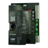
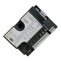
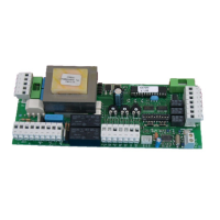
2. CONTROL PANEL FOR 230 V ac BARRIER
• MICROPROCESSOR-CONTROLLED LOGIC
• STATUS LEDS
• LINE FUSE
• BUILT-IN FLASHING LIGHT CIRCUIT
• BUILT-IN 433.92 MHz RADIO RECEIVER
• MAX. OPERATING TIME 40”
• AUTOMATIC 50 / 60 HZ FREQUENCY DETECTION
• ADJUSTABLE SOFT-STOP
• COMPATIBILITY WITH OUR APPS: TAUOPEN AND TAUAPP
ATTENTION:
- In case of long sections of cables (> 20 m) for N.O./N.C. controls (e.g. OPEN / CLOSE, STOP, PEDESTRIAN, etc.), in order to avoid gate mal-
functions, it will be necessary to uncouple the various controls using RELAYS or using our 750T-RELE device.
3. TESTING
Once the connection has been completed:
• All the green LEDs must be ON (each of them corresponds to a Normally Closed input). They will turn OFF when the controls to which they
are associated are operated.
• The red opening command LEDs must be OFF (each corresponding to a Normally Open input). They will turn ON when the commands they
are associated with are given; red LED DL1 must be ON steadily.
4. TECHNICAL CHARACTERISTICS
Power input – control board 230 V ac - 50-60 Hz
Nominal power 400 W
230 V AC Input protection fast blow fuse (F1 - 5x20) F 3,15 A
Power input – motors 230 V ac
Power input – auxiliary circuits 24 V ac
24 V ac Input (auxiliary circuits) fast blow fuse (F2 - 5x20) F 500 mA
Working temperature -20°C ÷ +55°C
Protection degree IP 44
5. DIAGNOSTICS LED
DL1 (RADIO CONTROLS) / RED ERROR message / PROGRAMMING of transmitters
DL2 (OPEN/CLOSE) / RED OPEN / CLOSE pushbutton activated
DL3 (PHOTO) / GREEN PHOTOCELL activated
DL4 (CLOSE LIMIT SWITCH) / GREEN indicator led for the DECELERATION IN THE CLOSING maneuver
DL5 (OPEN LIMIT SWITCH) / GREEN indicator led for the DECELERATION IN THE OPENING maneuver
DL6 (STOP) / GREEN STOP pushbutton activated
 Loading...