8
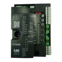
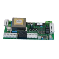
6. TERMINAL BOARD CONNECTIONS
Terminals Function Description
1 + 2 POWER SUPPLY POWER input 230/115 V AC 50-60 Hz. 1= NEUTRAL 2= PHASE;
3 + 4 FLASHING LIGHT
FLASHING LIGHT output 230/115 V AC, max. 50 W. The signal is already modulated for direct use; fast ashing
during closing, slow during opening. 3= 230/115 V AC, 4= 0 V AC;
5 - 6
LED
FLASHING LIGHT
FLASHING LIGHT Output FLASHING 12 VDC. Intermittent output during the operation, the ashing frequency is
doubled during closing;
7 + 10 OPEN/CLOSE OPEN/CLOSE input (Normally Open contact);
8 + 10 STOP STOP input (Normally Closed contact);
9 + 10 PHOTOCELLS
PHOTOCELLS OR SAFETY DEVICES input; active during closure (Normally Closed contact); the automation will
stop during closing and totally reopen it, (10= Common). If there is more than one safety device, connect all the
NC contacts IN SERIES.
11 + 12
24V AC
PHOTOCELLS
24 V AC 10 W output to Photocells, Receivers etc.; connect a up to 3 pair of photocells. 11= 0 V AC, 12= 24 V AC;
13 + 14 AERIAL 433,92 MHz built-in RX aerial input; 13= EARTH, 14= SIGNAL;
M2 MICRO SWITCH
Quick coupling for MICRO SWITCH connection (Normally Closed contacts). ORANGE= Micro Switch deceleration
in the closing maneuver (CLS), RED= Micro Switch Deceleration in the opening maneuver (OLS), GREY= Common
(COM);
FS1 + FS2 CAPACITOR CAPACITOR Terminals for motor start-up;
M3 MOTOR
Quick coupling for 230 V AC single-phase MOTOR connection. BLUE= common (M-COM);
BROWN= closing (M-CL); BLACK= opening (M-OP).
J4 APP quick plug-in for device connection for APP operation (mod. T-WIFI / T- CONNECT)
SM MEMORY CARD quick plug-in for MEMORY CARD connection for transmitters codes.
7. TRIMMER ADJUSTMENTS
FR.
Motor torque adjustment. Turning the trimmer clockwise (+) the torque will be increased; Turning the trimmer counterclockwise (-)
the torque will be decreased.
Note: The trimmer is set to provide sucient thrust to work the automation within the limits established by current
standards (EN 12453).
SENS.
It allows you to adjust the detection sensitivity of the mechanical limit switches. By turning the trimmer clockwise (+) the detec-
tion of the limit stop will be more sensitive. On the contrary, by turning counterclockwise (-) the sensibility will decrease. With
the trimmer in the minimum position, the motor will remain powered for the total time set by the dip switch n° 6 even though
the mechanical limit switch has been already reached. It is therefore necessary to adjust it correctly to avoid motor overheating.
T.C.A.
Automatic closing time adjustment. Turning the trimmer clockwise (+) time will be increased; Turning the trimmer counterclockwise
(-) the time will be decreased.
Note: The time values can be set between 1 and 120 seconds.
8. LIMIT SWITCH ADJUSTMENT
The microswitches control the deceleration of the barrier both during closing and opening maneuvers. Adjust the limit switch cams at the point
where you want the barrier to start the deceleration in both opening and closing maneuvers.
9. DIP SWITCH
1
AUTOMATIC
CLOSING
On automatic closing enabled.
O automatic closing disabled.
2 2 / 4 STROKE
On (with Automatic closing enabled) Two-Stroke operation mode OPEN-CLOSE, OPEN-CLOSE, etc.
O
(with Automatic closing enabled) Four-Stroke operation mode OPEN-STOP-CLOSE-STOP, OPEN-STOP-CLOSE-
STOP, etc.
3 NO REVERSE
On the automation ignores the close command while it is opening (NO REVERSE);
O the automation behaves according to the position of dip-switch n° 2;
4
OPENING
DIRECTION
On Left-hand leaf opening mode;
O Right-hand leaf opening mode;
5 NOT USED
O
keep it in the OFF position
6 OPERATING RANGE
On 8 seconds for RBLO-LE
O 4 seconds for RBLO-E
10. SETUP STROKE PROCEDURE
It is not required to memorize the stroke because the control unit uses the working times. With the dip switch n° 6 set the desired working time
based on the type of the barrier used (RBLO-LE/ RBLO-E).
The motor will be powered for the entire duration of the set time, regardless of whether the mechanical limit switches have been reached.
If the set time is higher than the actual time taken by the automation to open or to close you will have to adjust the Trimmer SENS so you can
allow an early stop once the mechanical limit switch has been reached.
 Loading...