Do you have a question about the tau D705M and is the answer not in the manual?
Disconnect power before opening. Read all instructions before installation.
Product must be installed by a qualified fitter. Ensure correct cable cross-section and dry location.
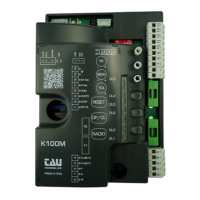
Check LED status after connections. Green LEDs ON for NC inputs, RED LEDs OFF for NO inputs.
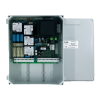
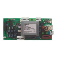
Details power input, fuses, voltage, temperature, and IP rating of the control unit.
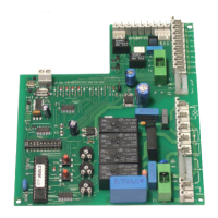
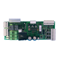
Lists terminals, functions, and descriptions for power, motor, and auxiliary connections.
Inputs for OPEN/CLOSE, OPEN, and CLOSE buttons. Functionality depends on dip switches.
Inputs for photocells, safety edges, limit switches, and microswitches for safe operation.
Outputs for 2nd Radio Channel, warning lights, and power for photocell transmitters/receivers.
Connections for antenna input and encoder for motor feedback and obstacle detection.
Adjusts Work Time (T.L.), Automatic Closing Time (T.C.A.), and obstacle sensitivity (FR).
Covers automatic closing, photocell operation, reverse, encoder, radio channel, and braking settings.
Features like Clock Function, Gate Open Contact, and Pedestrian opening via 2nd radio channel.
Step-by-step guide to associate radio control devices with the OPEN/CLOSE and 2nd channel functions.
Procedure for remote self-learning of new transmitters T-4RP and K-SLIM-RP (V 4.X).
Procedure to cancel all associated radio control devices using button P1 or P2.
Explanation of LED indicators, error flashes, and their meanings for diagnosing issues.
Solutions for automation not starting, poor radio range, and incorrect gate movement.
Cases not covered by warranty: improper installation, use of non-original parts, Acts of God, wear.
| Brand | tau |
|---|---|
| Model | D705M |
| Category | Control Panel |
| Language | English |