3
Models 702/741/772 To the Installer
110616
S Stationary appliances which are not
equipped with a power cord and a plug or
another device to disconnect the appliance
from the power source must have an all-pole
disconnecting device with a contact gap of
at least 3 mm installed in the external
installation.
S Appliances that are permanently connected
to fixed wiring and for which leakage
currents may exceed 10 mA, particularly
when disconnected, not used for long
periods, or during initial installation, shall
have protective devices such as a GFI to
protect against the leakage of current and
be installed by authorized personnel to the
local codes.
S Supply cords used with this unit shall be
oil-resistant, sheathed, flexible cable, not
lighter than ordinary polychloroprene or
other equivalent synthetic
elastomer-sheathed cord (Code designation
60245 IEC 57) installed with the proper cord
anchorage to relieve conductors from strain,
including twisting at the terminals, and
protect the insulation of the conductors from
abrasion.
Check Out
Once the unit is installed, it is advisable to check the
following controls and mechanical operations of the
freezer and make any necessary adjustments. If
applicable, repeat these checks for the second
freezing cylinder on double head units.
Controls
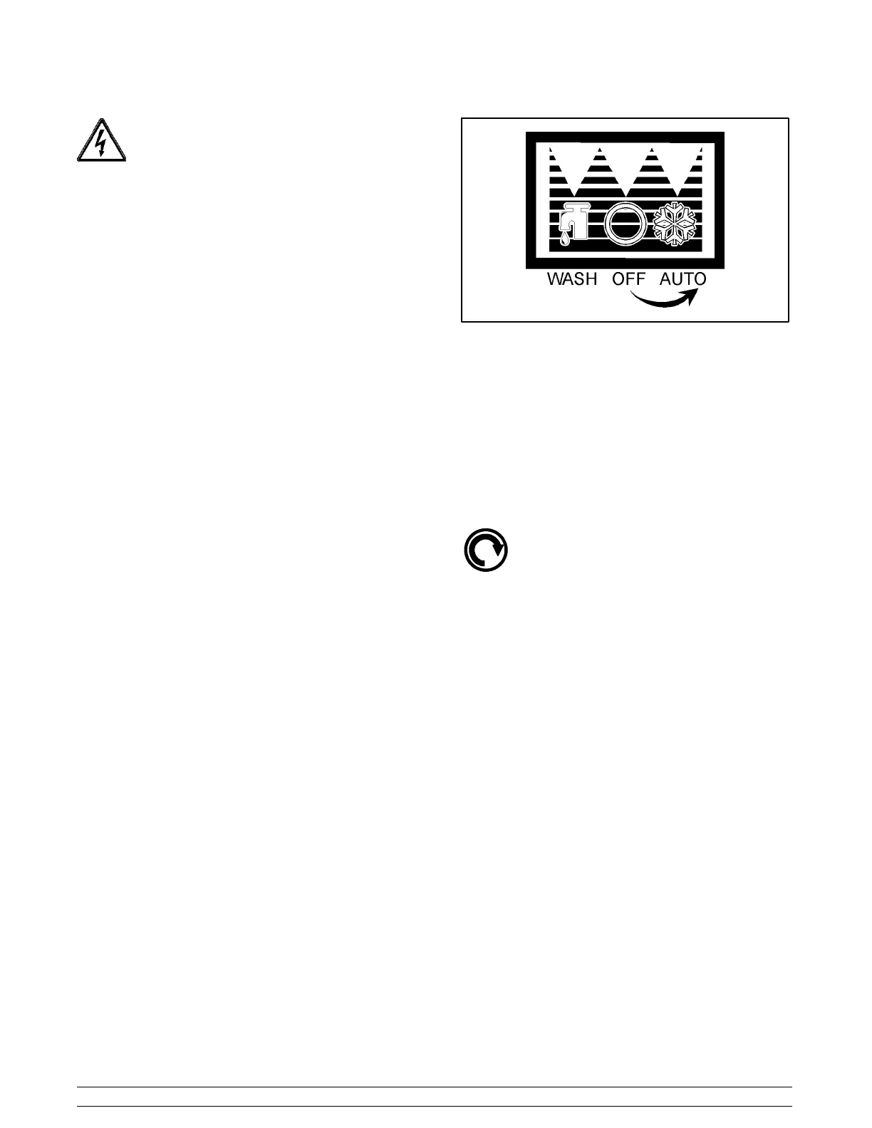
Place the control switch in the “AUTO” position. The
main refrigeration system will operate (compressor,
beater motor, and the condenser fan). The dial light
and the mix low indicator will be lit.
Figure 1
If the freezer is water cooled, the automatic water
valve will begin to open and cold water will flow into the
condenser. This will remove heat from the refrigerant.
As the water flows into the open trap drain, it should be
warm to the touch. Place the control switch in the
“OFF” position.
Beater Rotation
Beater rotation must be clockwise as viewed
looking into the freezing cylinder.
Note: The following procedures must be
performed by an authorized Taylor service
technician.
To correct rotation on a three-phase unit, interchange
any two incoming power supply lines at the freezer
main terminal block only.
To correct rotation on a single-phase unit, exchange
leads inside the beater motor. (Follow the diagram
printedonthemotor.)
Electrical connections are made directly to the
terminal block provided in the main control box located
behind the upper left side panel for the Model 702, and
behind the service panel for the Model 741 and 772.