Section 5Section 5
Cooling SystemCooling System
Introduction.Introduction. The cooling system cools theThe cooling system cools the
enginengine. e. RefRefer ter tooSection 9ASection 9Afor transmissionfor transmission
cooling andcooling andSection 15CSection 15Cfor the wet disc brakesfor the wet disc brakes
cooling system to find more detailed cooling infor-cooling system to find more detailed cooling infor-
mation on these particular systems.mation on these particular systems.
Major ComponentsMajor Components(Illustration 5-5)(Illustration 5-5).. The engine The engine
cooling system consists of coolant, radiator /cooling system consists of coolant, radiator /
charge air cooler, piping connecting the radiator tocharge air cooler, piping connecting the radiator to
the engine and a water pump to circulate the cool-the engine and a water pump to circulate the cool-
ant. ant. A coolant filA coolant filterter, remote mount, remote mounted, is used toed, is used to
filter and condition the coolant.filter and condition the coolant.
OperationOperation(Illustration 5-5)(Illustration 5-5).. When the engine isWhen the engine is
started, the water pump draws coolant from thestarted, the water pump draws coolant from the
radiator intradiator into the engine block. o the engine block. The coolant is cThe coolant is cir-ir-
culated through the engine and the coolant filterculated through the engine and the coolant filter
until it reaches a temperature of approximatelyuntil it reaches a temperature of approximately
180180
__
F, at which point the thermostat will start toF, at which point the thermostat will start to
open. open. This wiThis will allow cll allow coolant flow bacoolant flow back into the topk into the top
of the radiator corof the radiator core. e. Air trapped in the coolAir trapped in the coolant willant will
travel to the top of the deairation space by meanstravel to the top of the deairation space by means
of the deaeration line and an internal deaerationof the deaeration line and an internal deaeration
stand tube. stand tube. Coolant is Coolant is made availmade available from table from thehe
deaeration tank to displace the removed air bydeaeration tank to displace the removed air by
way of the make-up line.way of the make-up line.
Coolant.Coolant. The cooling system of this equipment isThe cooling system of this equipment is
protected to -34protected to -34
__
F (-36F (-36
__
C) and 228C) and 228
__
F (108.9F (108.9
__
C).C).
The solution is a 50 - 50 mixture of ethylene glycolThe solution is a 50 - 50 mixture of ethylene glycol
base antifreezbase antifreeze to water solute to water solution. ion. Use soft waUse soft waterter
in the coolant miin the coolant mixture. xture. It is recomIt is recommended thatmended that
50% solution be maintained year round.50% solution be maintained year round.
A A proper proper coolant coolant / / SCA SCA (Supplement(Supplemental al CoolantCoolant
Additive) Additive) additive additive concentration concentration must must be be main-main-
tained to prevent liner pitting, corrosion and scaletained to prevent liner pitting, corrosion and scale
deposits in the cooldeposits in the cooling systeming system. . Refer to theRefer to the
Cummins QSM11 Engine Operation and Mainte-Cummins QSM11 Engine Operation and Mainte-
nance Manual for coolant additive concentration.nance Manual for coolant additive concentration.
The coolant additive concentration level may beThe coolant additive concentration level may be
tested with a coolant test kit, Taylor part numbertested with a coolant test kit, Taylor part number
1006-175.1006-175.
CAUTION:CAUTION:Insufficient concentration ofInsufficient concentration of
the coolant additives will result in liner pittingthe coolant additives will result in liner pitting
and engine and engine failurfailure.e.
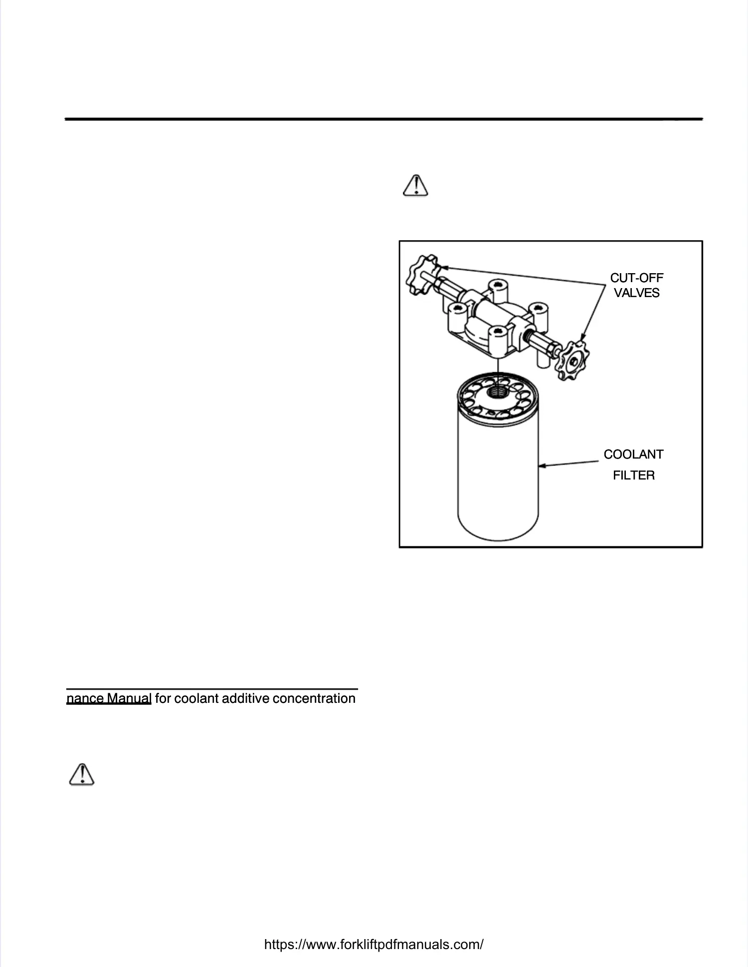
Coolant FilterCoolant Filter(Illustration 5-1)(Illustration 5-1).. The coolant filterThe coolant filter
is used in the cooling system to control the wateris used in the cooling system to control the water
acidity, soften the water to reduce scale formation,acidity, soften the water to reduce scale formation,
filter out suspended materials and add a corrosionfilter out suspended materials and add a corrosion
inhibiting chemical to the coolant which provides ainhibiting chemical to the coolant which provides a
protective film on the water passages.protective film on the water passages.
CAUTION:CAUTION:Coolant containing anti-leakCoolant containing anti-leak
additives must not be used with the coolantadditives must not be used with the coolant
filter because it will clog the element.filter because it will clog the element.
COOLANTCOOLANT
FILTERFILTER
CUT-OFFCUT-OFF
VALVESVALVES
IllustrIllustration 5-1. ation 5-1. Coolant FiCoolant Filterlter
Radiator / Charge Air CoolerRadiator / Charge Air Cooler(Illustration 5-4)(Illustration 5-4)..
The radiator is comprised of a deaeration tank,The radiator is comprised of a deaeration tank,
core, and a charge air ccore, and a charge air coolerooler. . The deaerationThe deaeration
tank functitank functions as a coolons as a coolant storage tant storage tank. ank. WhenWhen
adding coolant to the system, coolant should beadding coolant to the system, coolant should be
added to the deaeratiadded to the deaeration tank. on tank. Access tAccess to theo the
deaeration tank is supplied through a 7 psi radia-deaeration tank is supplied through a 7 psi radia-
tor cap located on the left side of the radiator,tor cap located on the left side of the radiator,
above the radiatabove the radiator sight glor sight glasses. asses. The radiatorThe radiator
coolant level is to be maintained by the coolantcoolant level is to be maintained by the coolant
sight glasses below the 7 psi radiator cap.sight glasses below the 7 psi radiator cap.
The radiator is forThe radiator is force-air-ce-air-cooled. cooled. Access to theAccess to the
core is supplied through a 15 psi radiator capcore is supplied through a 15 psi radiator cap
located on the right slocated on the right side of the radiatoride of the radiator. . When theWhen the
cooling system has been completely drained, thecooling system has been completely drained, the
15 psi radiator cap neck will allow a quicker, more15 psi radiator cap neck will allow a quicker, more
efficient method of refilling the cooling system.efficient method of refilling the cooling system.
Charge Air CoolerCharge Air Cooler(Illustration 5-4)(Illustration 5-4).. The QSM11 The QSM11
engine is equipped with a trubocharger. Theengine is equipped with a trubocharger. The
turbocharger is driven by the exhaust from theturbocharger is driven by the exhaust from the
engine. The exhaust turbine of the turbocharger isengine. The exhaust turbine of the turbocharger is
coupled to the incoupled to the intake turbitake turbine. ne. The exhaust tThe exhaust turbineurbine
drives the intake turbine. The intake turbine com-drives the intake turbine. The intake turbine com-
 Loading...