Installation, Operation & Maintenance Manual
IM-4055
Always disconnect power before inspection or maintenance.
Although motor may be o and not running when a 0-1.9V DC
signal is present, high voltage will still be present at the motor.
CAUTION
Twin City Fan
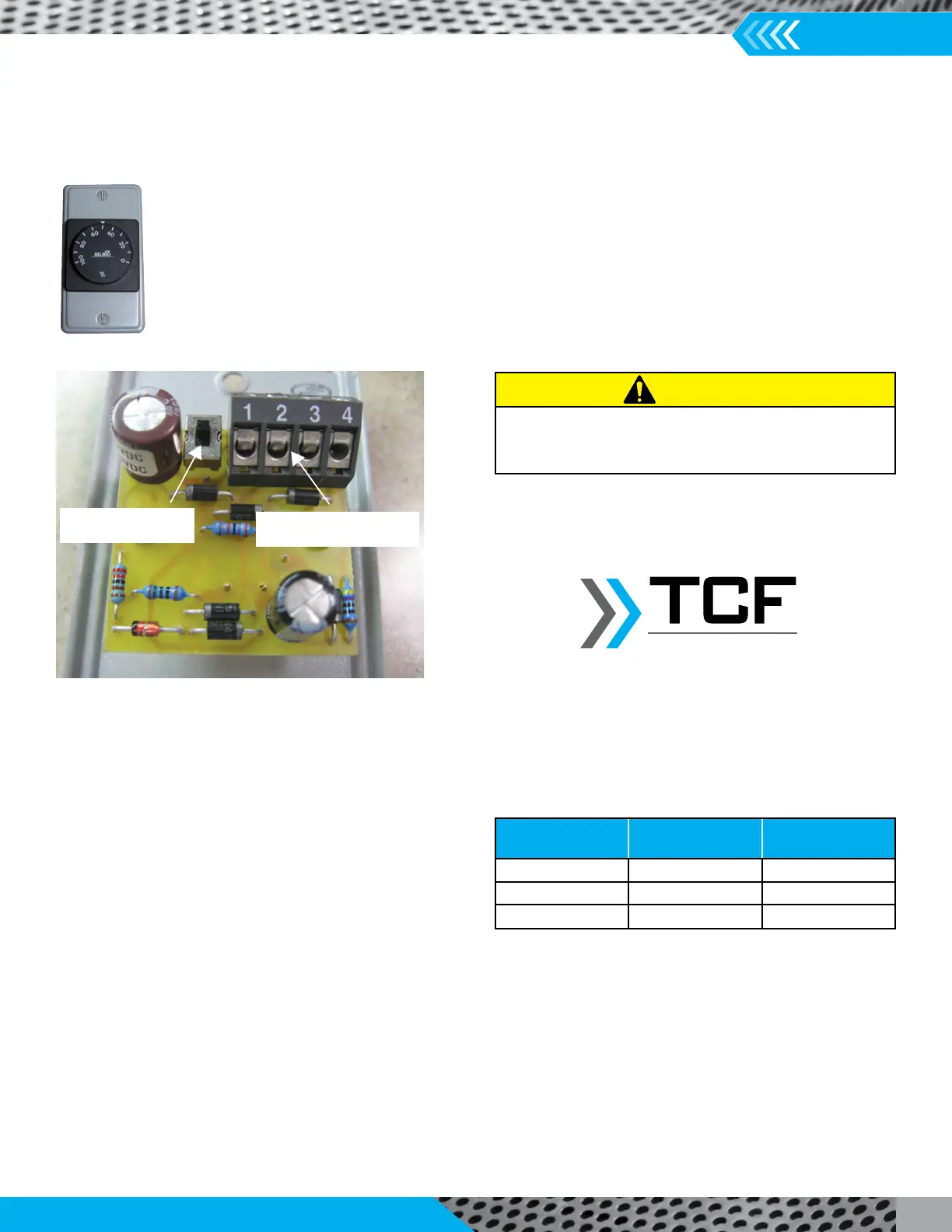
DIAL OUTPUT
SELECTION SWITCH
3 WIRE CONTROL CABLE
CONNECTION TERMINALS
Note: This section refers to motors 67001001, 67001003, 67001004, 67001005,
67001008, 67001015, 67001103, 67001104, 67001105, 6700115, 67001701,
67001703, 67001704, 67001705, 67001715, 67002101, 67002107, 67002205.
Speed Control Options: ODP & TENV Motors (cont.)
4. Remote Mounted Dial, RMD (Optional Feature) – A wall mounted dial allows the fan to be controlled from within the building
24V AC transformer mounted in the NEMA electrical enclosure. On models DCRD, DCRU/R, DCRW/R, DCLH/P
100 feet. Distances greater than this could cause a loss of the signal to the motor and result in unstable motor
performance.
On the back of the remote mounted dial there is a small switch that will allow the user to change the output of the remote
made as shown in table to the right:
The user should verify that the dial is properly working
by adjusting the dial and checking that the motor speed
changes accordingly. The voltage at the dial should also be
Terminals 1 and 3 should have a DC voltage in the range of
Note that the motor mounted dial acts as a speed reference for this option. In order to have the full speed control range
available for a given fan/motor combination, the motor mounted dial must be turned all the way in the CW direction or to the
Figures 1, 2 and 3 are detailed wiring diagrams for the Remote Mounted Dial option.
Connecon in
Transformer Box
Descripon
Terminal on
Back of Dial
Yellow/White Common 1
Blue/Black 24V AC 2
Red 0-10V DC 3
 Loading...