EasyManua.ls Logo

TCL TAC-09CHSA/XP

TCL TAC-09CHSA/XP
40 pages
To Next Page IconTo Next Page
Loading...
Air Conditioner Service Manual
Inverter air conditioner
Service Manual
Models
TAC-09CHSA/XP TAC-12CHSA/XP
CONTENTS
1. Important Notice
2. Technical Specifications
3. Product Dimensions
4. Refrigeration cycle diagram
5. Operation details
6. Wiring diagram
7. Explosion view and parts
8. Precaution
9. Names of parts
10. Installation
11. Trouble shooting
Question and Answer IconNeed help?

Do you have a question about the TCL TAC-09CHSA/XP and is the answer not in the manual?

TCL TAC-09CHSA/XP Specifications

General IconGeneral
Cooling Capacity9000 BTU/h
Heating Capacity9500 BTU/h
Energy Efficiency Ratio (EER)3.21
RefrigerantR410A
Power Supply220-240V, 50Hz
Weight (Indoor Unit)9 kg
TypeSplit Type
Outdoor Unit Dimensions (W x H x D)700 x 500 x 240 mm

Summary

1. Important Notice

How to Order Spare Parts

Instructions for ordering spare parts for the air conditioner.

2. Technical Specifications

3. Product Dimensions

4. Refrigeration Cycle Diagram

5. Operation Details

Remote Controller Functions

Explains the buttons and operation of the remote control.

Electronic Controller Safety Protection

Electronic Controller Operation Modes

Feel and COOLING Mode Operation

Details "Feel" and "COOLING" mode operations and settings.

Electronic Controller Mode Operations

DRY and HEATING Mode Operation

Details DRY and HEATING mode operations.

Electronic Controller Special Functions

Sleep, Emergency, and Auto-Restart Functions

Covers SLEEP, Emergency, and Auto-Restart functions.

Protection and Failure Display

Explains how the unit displays protection codes and failures.

Error List and Protection Codes

Protection Display Code List

Details protection types and their indicator codes.

Outdoor Unit Failure Display

6. Wiring Diagram

7. Explosion View and Parts - Indoor Unit

7. Explosion View and Parts - Indoor Unit (cont.)

7. Explosion View and Parts - Outdoor Unit

7. Explosion View and Parts - Outdoor Unit (cont.)

8. Precaution - Installation Safety

8. Precaution - User Safety

8. Precaution - Prohibitions

9. Names of Parts

Indoor and Outdoor Unit Parts

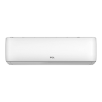
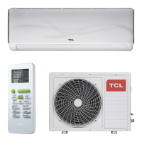
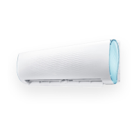
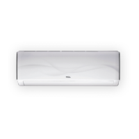
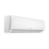
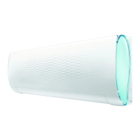
Lists and identifies parts of the indoor and outdoor units.

10. Installation Manual - Installation Details

10. Installation Manual - First Time Installation

10. Installation Manual - Mounting Plate and Piping

10. Installation Manual - Refrigerant Piping and Drainage

10. Installation Manual - Electronic Connections and Bleeding

11. Trouble Shooting - Outdoor Control Diagram

11. Trouble Shooting - ODU PCB Structure and Connection

11. Trouble Shooting - Current Flow and ODU PCB Connection

11. Trouble Shooting - Repair Examples (E1, E2, E6)

11. Trouble Shooting - Repair Examples (E3, E7, E8)

11. Trouble Shooting - Repair Examples (E0, E5)

11. Trouble Shooting - Repair Examples (E9, EU, EE)

11. Trouble Shooting - Display CL and Malfunction Check

11. Trouble Shooting - DC Over Current Error

11. Trouble Shooting - E0,E5 Error Flowchart

11.7 Thermistor Temperature Characteristics

11.7 Thermistor Temperature Characteristics Data

11.7 Thermistor Temperature Characteristics Data (cont.)

11.7 Thermistor Temperature Characteristics Data (cont.)

Related product manuals