Do you have a question about the TCL TAC-09CHSA/XA71 and is the answer not in the manual?
Provides essential information for ordering replacement parts, including model numbers and part names.
Details on the electronic controller's safety mechanisms to protect the unit and prevent damage.
Explains the functionality and temperature settings for the 'Feel' mode operation.
Describes compressor frequency control and fan speed adjustments during cooling.
Details the system's operation in DRY mode, including fan speed and compressor control.
Covers frequency control, cold air prevention, and auto fan control for heating.
Explains the operation of the 4-way valve during heating and defrosting cycles.
Describes the conditions and process for initiating and exiting the defrosting cycle.
Details the protection mechanism for the indoor heat exchanger against overheating.
Explains how the unit adjusts settings and operates in SLEEP mode for comfort.
Describes how to activate emergency operation mode for testing or when the remote is unavailable.
Details the function that restores the unit to its previous settings after a power interruption.
Explains how error codes and protection indicators are displayed on the unit.
Guidelines for safely installing the air conditioner, including electrical and environmental considerations.
Recommendations for safe operation, maintenance, and general usage of the air conditioner.
Lists prohibited actions and conditions to avoid during operation and installation to ensure safety.
Specifies pipe sizes and maximum lengths for connecting indoor and outdoor units.
General guidelines for installing the indoor and outdoor units, including placement and clearances.
Step-by-step instructions for mounting the indoor unit, drilling holes, and making electrical connections.
Instructions for refrigerant piping, connecting pipes, and bleeding the system for proper operation.
Diagram illustrating the control system and communication between indoor and outdoor units.
Overview of the Outdoor Unit PCB components and their interconnections.
Illustrates the path of electrical current flow between the indoor unit PCB and outdoor unit PCB.
Provides common error codes (E1, E2, E6, E3, E7, E8) and their troubleshooting steps.
Flowcharts for diagnosing issues like IPM/compressor malfunctions and DC overcurrent errors.
Detailed troubleshooting steps for specific error codes such as E0, E5, and general PCB issues.
Table of resistance values for indoor temperature and exchange temperature sensors at various temperatures.
Table showing resistance values for outdoor unit sensors at different temperature readings.
| Cooling Capacity | 9000 BTU/h |
|---|---|
| Heating Capacity | 9500 BTU/h |
| Energy Efficiency Ratio (EER) | 3.21 |
| Power Supply | 220-240V, 50Hz |
| Refrigerant | R32 |
| Compressor Type | Rotary |
| Power Consumption (Cooling) | 840 W |
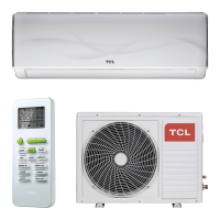
| Type | Split |