Do you have a question about the TCL Inverter TAC-09CHSD/XAB1I and is the answer not in the manual?
| Brand | TCL |
|---|---|
| Model | Inverter TAC-09CHSD/XAB1I |
| Category | Air Conditioner |
| Language | English |
Instructions for ordering replacement parts, including necessary information.
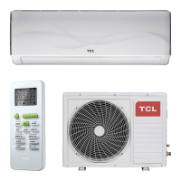
Explanation of buttons and their functions on the air conditioner remote control.
Details on various safety protections implemented in the electronic controller.
Explains the 'Feel' and 'Cooling' modes, including temperature and fan control.
Details the 'Dry' and 'Heating' modes, including fan speed and frequency control.
Covers 4-way valve control, defrosting, and overheat protection functions.
Describes 'Sleep', 'Emergency', and 'Auto-Restart' modes and functions.
Lists error codes and protection display codes for system faults.
Explains the meaning of LED indicators on the outdoor unit for failures.
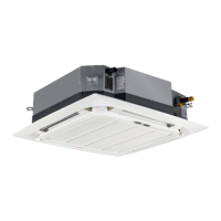
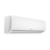
Exploded view and list of parts for the indoor unit model TAC-09CHSD/XAB1I.
Exploded view and list of parts for the outdoor unit model TAC-09CHSD/XAB11.
Exploded view and list of parts for the indoor unit model TAC-12CHSD/XAB11.
Exploded view and list of parts for the outdoor unit model TAC-12CHSD/XAB11.
Exploded view and list of parts for the indoor unit model TAC-18CHSD/XAB11.
Exploded view and list of parts for the outdoor unit model TAC-18CHSD/XAB11.
Exploded view and list of parts for the indoor unit model TAC-24CHSD/XAB11.
Exploded view and list of parts for the outdoor unit model TAC-24CHSD/XAB11.
Exploded view and list of parts for the indoor unit model TAC-09CHSD/XAB1IHB.
Exploded view and list of parts for the outdoor unit model TAC-09CHSD/XAB1IHB.
Exploded view and list of parts for the indoor unit model TAC-12CHSD/XAB1IHB.
Exploded view and list of parts for the outdoor unit model TAC-12CHSD/XAB1IHB.
Exploded view and list of parts for the indoor unit model TAC-18CHSD/XAB1IHB.
Exploded view and list of parts for the outdoor unit model TAC-18CHSD/XAB1IHB.
Exploded view and list of parts for the indoor unit model TAC-24CHSD/XAB1IHB.
Exploded view and list of parts for the outdoor unit model TAC-24CHSD/XAB1IHB.
General safety rules and recommendations for installing the air conditioner.
Safety rules and recommendations for users operating the air conditioner.
Lists prohibitions and warnings to ensure safe operation and prevent hazards.
Specifications for connecting pipes and refrigerant charge for different models.
Recommendations for indoor and outdoor unit placement to ensure proper operation and airflow.
Steps for installing the mounting plate, drilling holes, and making indoor unit electrical connections.
Details on connecting refrigerant pipes, managing condensate drainage, and other connections.
Instructions for outdoor unit electrical connections and the bleeding process.
Solutions for troubleshooting error codes E1, E2, and E6 related to sensors and motors.
Solutions for troubleshooting error codes E3, E7, and E8 related to temperature sensors.
Solutions for troubleshooting error codes E0, E5, EA related to communication and current sensors.
Solutions for troubleshooting error codes E9 and EU related to PCB drive and voltage sensors.
Solution for troubleshooting error code EE related to EEPROM fault.
Flowchart for diagnosing defective outdoor unit IPM or compressor malfunctions.
Troubleshooting steps for DC over current errors, covering various components and checks.
Detailed troubleshooting steps for E0 and E5 errors, focusing on communication issues.
Introduction to R32/R290 refrigerants and their safety considerations.
Requirements for installation area and safety principles when handling refrigerants.
Checks required for the maintenance environment, equipment, and the air conditioner itself.
Procedures for leak inspection and safety principles during maintenance.
Guidelines for filling refrigerants, performing welding, and maintaining electrical components.
Details on maintaining electrical parts and handling emergency situations.