Do you have a question about the TCL Free Match TAC-12CHSD/XA41-I and is the answer not in the manual?
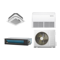
| Type | Split System |
|---|---|
| Cooling Capacity | 12000 BTU/h |
| Energy Efficiency Ratio (EER) | 3.21 |
| Coefficient of Performance (COP) | 3.61 |
| Power Supply | 220-240V, 50Hz |
| Power Consumption (Heating) | 1050 W |
| Noise Level (Outdoor) | 52 dB(A) |
| Refrigerant | R32 |
| Outdoor Unit Dimensions (WxHxD) | 720x495x270 mm |
| Indoor Unit Weight | 8.5 kg |
| Operating Temperature (Cooling) | 18°C to 43°C |
| Operating Temperature (Heating) | -7°C to 24°C |
Describes safety delays for compressor and 4-way valve to protect the system.
Details protection triggered by high discharge pipe temperature, leading to system shutdown.
Explains shutdown and recovery conditions based on low AC and DC voltage levels.
Details shutdown and recovery criteria for overvoltage conditions on AC and DC power.
Lists failure types, their corresponding indoor LED codes, cassette LED codes, and outdoor light blink times.
Details protection types, their codes, and how they are indicated on indoor and outdoor unit LEDs.
Provides essential safety rules and recommendations for correctly installing the air conditioner unit.
Emphasizes that installation and maintenance must be performed by specialized technical personnel.
Details precautions regarding mains voltage, power plug, and socket for safe operation.
Instructs to cut off power immediately and contact the service center if smoke or burning smell is detected.
Emphasizes that repairs should only be performed by authorized service centers to avoid risks.
Warns against damaging the power cord, which can lead to electrical shocks or fire hazards.
Prohibits the use of extension cords or gang modules for safety reasons.
Advises against touching the appliance with wet body parts to prevent electric shock.
Prohibits contact with water to prevent electrical insulation damage and electrocution risk.
Warns against inserting objects into the appliance, which can cause injury.
Mandates supervision of children to ensure they do not play with the appliance.
Details the three possible directions for running refrigerant pipes from the indoor unit.
Advises not to remove pipe caps until connection to prevent dirt entry.
Instructions on removing the indoor unit pipe cap and preparing for connection.
Details on inserting the flare nut and creating a flange for secure pipe connections.
Describes the correct method for tightening pipe connections using two wrenches.
Describes screw tightening of flare nuts on outdoor unit couplings with specific torque procedures.
Warns about potential leakage due to insufficient tightening torque on flanges.
Explains that bleeding air/humidity prevents compressor malfunction.
Details the process of bleeding air and humidity from the refrigerant circuit using a vacuum pump.
Details causes, sensor checks, and PCB replacement for E1/E2 errors.
Covers causes, motor connection checks, and PCB replacement for E6 errors.
Identifies loose sensor connections or damaged sensors as reasons for E3/E7 errors.
Provides solutions for E8 errors, involving sensor connections, damage, and outdoor PCB.
Guides through resolving E0/E5 communication errors via voltage and PCB checks.
Check terminal L and N voltage on the indoor unit; replace PCB if voltage is 0V.
Measure outdoor terminal voltage (0-24V); replace indoor PCB if abnormal.
Measure outdoor terminal voltage (0-12V); replace outdoor PCB if 24V is missing.
Check outdoor terminal voltage; replace indoor PCB first, then outdoor PCB if fault persists.
Check optical coupler/resistance for communication faults; replace outdoor PCB or other components if burnt.
Test DC voltage between DC+ and DC- to diagnose E0/E5 errors.
Identifies a current sensor fault as the reason for the EA error display.
Check for refrigerant leaks and replace outdoor PCB if the current sampling circuit is broken.
States that damage to the outdoor PCB drive circuit causes E9 errors.
Checks system pressure, ventilation, and recommends PCB replacement if E9 persists.
Verifies P9 protection code and U,V,W connections for E9 errors.
Resolves EU errors caused by voltage sensor damage by replacing the outdoor PCB.
Addresses EE errors due to EEPROM faults, recommending PCB checks and replacement.
Flowchart for diagnosing outdoor unit IPM/compressor startup failures and DC overcurrent.
Checks valve status, compressor rotation, run time, and IPM PWB seating.
Verifies AC power voltage, mode, and checks indoor/outdoor sensors and heat exchange.
Inspects refrigerant amount, indoor/outdoor heat exchange for DC over current issues.
Includes initial PCB replacement, power cycling, and wire connection checks for E0/E5.
Detailed voltage checks and corresponding PCB replacement strategies for E0/E5 errors.