EasyManua.ls Logo

TCL FMA-09CHSD/DVI

TCL FMA-09CHSD/DVI
58 pages
To Next Page IconTo Next Page
Loading...
TCL Air Conditioner Service Manual
TCL Multi Inverter air conditioner
Service Manual
Models
FMA-09CHSD/DVI FMA-12CHSD/DVI
FMA-09CRD/DVI(Q4) FMA-12CRD/DVI(Q4)
FMA-18CRD/DVI(Q4) FMA-09D5RD/DVI
FMA-12D5RD/DVI FMA-18D5RD/DVI
FMA-18I2HD/DVO FMA-27I3HD/DVO
FMA-30I4HD/DVO
CONTENTS
1. Important Notice
2. Product Dimensions
3. Refrigeration cycle diagram
4. Operation details
5. Wiring diagram
6. Explosion view and parts
7. Precaution
8. Names of parts
9. Installation
10. Trouble shooting
11. Introduction R32/R290 air conditioner installation
Question and Answer IconNeed help?

Do you have a question about the TCL FMA-09CHSD/DVI and is the answer not in the manual?

TCL FMA-09CHSD/DVI Specifications

General IconGeneral
BrandTCL
ModelFMA-09CHSD/DVI
CategoryAir Conditioner
LanguageEnglish

Summary

Important Notice

How to order spare parts

Instructions for ordering replacement parts, requiring specific details.

Product Dimensions

Indoor Unit: Wall split type

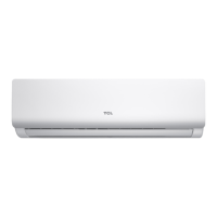
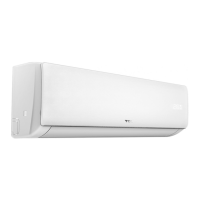
Provides dimensional data for the wall split type indoor unit.

Indoor Unit: Cassette type

Provides dimensional data for the cassette type indoor unit.

Indoor Unit: Duct type

Provides dimensional data for the duct type indoor unit.

Outdoor Unit

Refrigeration cycle diagram

OPERATION DETAILS

Remote controller

Details the buttons and functions of the air conditioner's remote controller.

Electronic Controller

1. Safety Protection

Outlines various safety protection mechanisms integrated into the electronic controller.

2. Feel Mode Operation

Describes the functionality and logic of the "Feel" mode operation.

3. COOLING Mode Operation

4.DRY Mode Operation

5. HEATING Mode Operation

2) Auto fan control (heating)

(3) 4-way valve control

(4) Outdoor fan motor control

(5) Defrosting

(5) Indoor exchanger overheat protection

5. SLEEP mode

6. EMERGENCY Operation

7. AUTO-RESTART Function (Option)

8. Water pump control(cassette and duct type)

9. Protection and Failure Display

Error list

Failure Type

Lists specific failure types with their associated indoor and outdoor LED codes.

Protection display code list:

Details protection types and their corresponding LED codes and blink times.

Outdoor failure display

5. Wiring diagram

INDOOR UNIT: Wall split type: FMA-09 CHSDDVI FMA-12 CHSDDVI

Detailed wiring diagram for specific wall split indoor unit models.

INDOOR UNIT: Cassette, Duct type...

Wiring diagrams for cassette and duct type indoor units.

OUTDOOR UNIT: ONE TO 2 TYPE: FMA-1812 HDDVO

OUTDOOR UNIT: ONETO 3 TYPE: FMA-2713 HDDVO

OUTDOOR UNIT: ONE TO 4 TYPE: FMA-3014 HDDVO

6. Explosion view and parts

Indoor Unit- FMA-09 CHSDDVI

Exploded view and part list for the FMA-09CHSD/DVI indoor unit.

Indoor Unit- FMA-12 CHSDDVI

Indoor Unit- FMA-09 CRDDVI(Q4)

Indoor Unit- FMA-12 CRDDVI(Q4)

Indoor Unit- FMA-18 CRDDVI(Q4)

Indoor Unit- FMA-09 D5 RDDVI

Indoor Unit- FMA-12 D5 RDDVI

Indoor Unit- FMA-18 D5 RDDVI

Outdoor Unit - FMA-1812 HDDVO

Outdoor Unit - FMA-2713 HDDVO

Outdoor Unit - FMA-3214 HDDVO

7. Precaution

7.1 SAFETY RULES AND RECOMMENDATIONS FOR THE INSTALLATION

Details crucial safety guidelines for installing the air conditioner unit.

7.2 SAFETY RULES AND RECOMMENDATIONS FOR THE USER

7.3 SAFETY RULES AND PROHIBITIONS

8. Names of parts

Wall split type

Lists and illustrates the names of parts for the wall split type indoor and outdoor units.

Indoor unit

Identifies key components of the indoor unit.

Outdoor unit

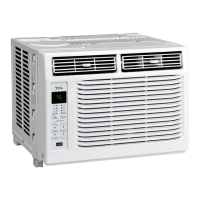
Identifies key components of the outdoor unit.

Display

Explains the indicators and symbols displayed on the unit's display panel.

Cassette type

Indoor Unit

Lists and labels parts of the cassette type indoor unit.

Outdoor Unit

Lists and labels parts of the cassette type outdoor unit.

Display

Explains the indicator lights for operation status and modes.

Duct type

Indoor Unit

Lists and labels parts of the duct type indoor unit.

Outdoor Unit

Lists and labels parts of the duct type outdoor unit.

DISPLAY

Explains the indicators on the unit's display panel for various functions.

9. Installation manual

9.1 Installation Details

Covers crucial installation details like pipe length and connecting cables.

9.2 Installation for the first time

Indoor unit

Provides guidelines for installing the indoor unit, including wall type considerations.

OUTDOOR UNIT

Provides guidelines for installing the outdoor unit, including placement and clearances.

9.2.1 Installation of the mounting plate.

Wall split type:

Step-by-step guide for mounting the plate for wall split units.

Cassette and Duct type:

Installation method for cassette and duct type units, including wooden construction.

9.2.2 Drilling a hole in the wall for the piping

How to mount outlet pipe.

9.2.3 Electrical connections-Indoor unit

9.2.4 Refrigerant piping connection

9.2.5 Connecting the pipes.

9.2.6 Connections to the indoor unit

9.2.7 Indoor unit condensed water drainage

9.2.8 Electronic connections of outdoor unit

9.2.9 Connecting the pipe of outdoor unit

9.2.10 Bleeding

10. Trouble shooting

10.1 Outdoor control diagram

Illustrates the control logic and communication pathways within the outdoor unit system.

10.2 The structure of ODU PCB

Details the layout and components of the Outdoor Unit Printed Circuit Board (ODU PCB).

10.3 Examples of repairing

10.3.1 Display E1 or E2

Troubleshooting steps for E1 or E2 error codes related to sensor issues.

10.3.2 Display E6

10.3.3 Display E3, E7

10.3.4 Display E8

10.3.5 Display E0,E5

10.3.6 Display EA

10.3.7 Display E9 (first display P0 or P9)

10.3.8 Display EU.

10.3.9 Display EE

10.3.10 Display CL

10.4 MALFUNCTION (PARTS) CHECK METHOD

10.4.1 Procedure for determining defective outdoor unit IPMcompressor

Flowchart for diagnosing issues with outdoor unit IPM and compressor startup.

10.4.3 E0,E5 Error

10.5 THERMISTOR TEMPERATURE CHARACTERISTICS

2. Outdoor unit sensor temperature characteristics

11. Introduction R32 R290 air conditioner installation

11.1 Introduction to Refrigerants R32 & R290

Discusses the properties and safety of R32 and R290 refrigerants.

Special tools:

Maintenance

1. Inspections before maintenance.

Details pre-maintenance checks for the environment and equipment.

2. Leak inspection before maintenance

4. Safety principles during the maintenance

5. Requirements for the site of maintenance-station

6. Requirements for fill the refrigerants

7. In-maintenance welding

8. Maintenance of electrical components

Warning

9. Emergency Accident Handling

Related product manuals