Do you have a question about the TCL U-MATCH-R32 Series and is the answer not in the manual?
Safety and usage guidelines for the service manual.
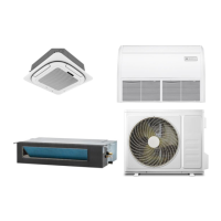
Lists available indoor and outdoor unit models with their specifications.
Comprehensive technical data for various unit types and models.
Detailed specifications for Cassette, Duct, and Ceiling/Floor units.
Static pressure curves for Duct type units across different capacities.
Sound power and pressure levels for Cassette, Duct, and Outdoor units.
Operating temperature, humidity limits, and usage cautions.
Dimensional drawings and specifications for indoor and outdoor units.
Wiring diagrams and switch configurations for different unit types.
Wiring diagrams and switch configurations for indoor units.
Wiring diagrams and switch settings for Duct type units.
Wiring diagrams and switch settings for Ceiling & Floor units.
Wiring diagrams for various outdoor unit models.
PCB layouts for indoor and outdoor units.
PCB layouts for Cassette, Duct, and Ceiling/Floor indoor units.
PCB layouts for 12K/18K and 24K/30K outdoor units.
Information on the built-in draining pump for different unit types.
Explanation of remote control display symbols and their meanings.
Introduction to wired remote controllers, icons, and dial settings.
Instructions for connecting and installing controller wiring for various unit types.
Crucial safety precautions for installation and maintenance tasks.
Safety measures for installing and relocating the air conditioner unit.
Guidelines for safe installation practices and site preparation.
Steps for responding to refrigerant leaks and other emergencies.
Criteria for selecting suitable locations for indoor and outdoor unit installation.
Specific guidelines for choosing indoor unit placement.
Specific guidelines for choosing outdoor unit placement.
Step-by-step instructions for installing indoor units.
Detailed steps for installing Cassette type indoor units.
Steps for installing Duct type indoor units.
Required space and hanging instructions for Duct units.
Options for air return and installation of air ducts.
Steps for installing outdoor units.
Required clearance and placement guidelines for outdoor units.
Principles and methods for installing drainage pipes.
Basic principles for drainage pipe installation.
Important considerations for drainage pipe installation.
Procedures for installing refrigerant pipes.
Pipe sizes and methods for refrigerant pipe installation.
Steps for connecting refrigerant pipes, including sizing and bending.
Procedures for vacuum drying and detecting leaks in the system.
Safety measures during vacuum drying and leak detection.
Guidelines and precautions for adding refrigerant to the system.
Importance, materials, and installation of refrigerant pipe insulation.
Steps for insulating refrigerant pipes.
General guidelines and safety precautions for electrical wiring.
Mandatory safety rules for electrical wiring work.
Steps for performing system tests after installation.
Explanation of indoor unit display board icons and error codes.
Flowchart for diagnosing IDU & ODU communication failures.
Flowchart for diagnosing room and coil temperature sensor failures.
Flowchart for diagnosing indoor unit ventilation (fan motor) failures.
Flowchart for diagnosing ODU sensor failures.
Flowchart for diagnosing outdoor unit DC fan motor failures.
Flowchart for diagnosing IPM overcurrent/overheat protection issues.
Flowchart for diagnosing over/under voltage protection.
Flowchart for diagnosing over current protection issues.
Flowchart for diagnosing ODU discharge temperature overheating.
Flowchart for diagnosing sub-cooling protection in Cooling/Dry mode.
Flowchart for diagnosing ODU overheating protection in Cooling mode.
Flowchart for diagnosing IDU overheating protection in Heating mode.
Flowchart for diagnosing outdoor over/under temperature protection.
Flowchart for diagnosing compressor phase or anti-phase protection.
Flowchart for diagnosing IPM module temperature protection.
Flowchart for diagnosing gas leakage protection.
Exploded views and parts lists for various outdoor unit models.
Exploded views and parts lists for Duct type indoor units.
Exploded views and parts lists for Cassette type indoor units.
Tables for temperature conversion and sensor resistance values.
Table of discharge temperature sensor values.
Table showing normal voltage ranges for P and N connections.
| Refrigerant | R32 |
|---|---|
| Power Supply | 220-240V, 50Hz |
| Operating Temperature (Heating) | -7-24°C |
| Type | Split Air Conditioner |
| Noise Level (Outdoor Unit) | 53 dB(A) to 56 dB(A) |