2800 LAURA LANE • MIDDLETON, WI 53562 • (800) 288-9383 • FAX (608) 836-9044 • www.tcsbasys.com
13
OVERRIDE ON
178 MINUTES
AUX HEAT 1 ON
REV VALVE CLOSED
5.
6.
7.
AUX HEAT 2 OFF
FAN STATUS OK
DI2 SERVICE OFF
FILTER OK
8.
MON 11-19-01
72F
12:00 AM
service
status
service
status
service
status
service
status
service
status
COMP STAGE 1 OFF
COMP STAGE 2 OFF
R
DISCHARGE AIR
55F
OUTDOOR AIR
75F
SERVICE STATUS
OK
TEMP
2.
3.
TEMP
service
status
service
status
service
status
fan
Occup ied
Heating
Cooling
Fan
Ser vic e
Program/
COOLER
WARMER
Data
swit ch
service
status
system
swit ch
program
setup
clock
setup
override
11-19-01
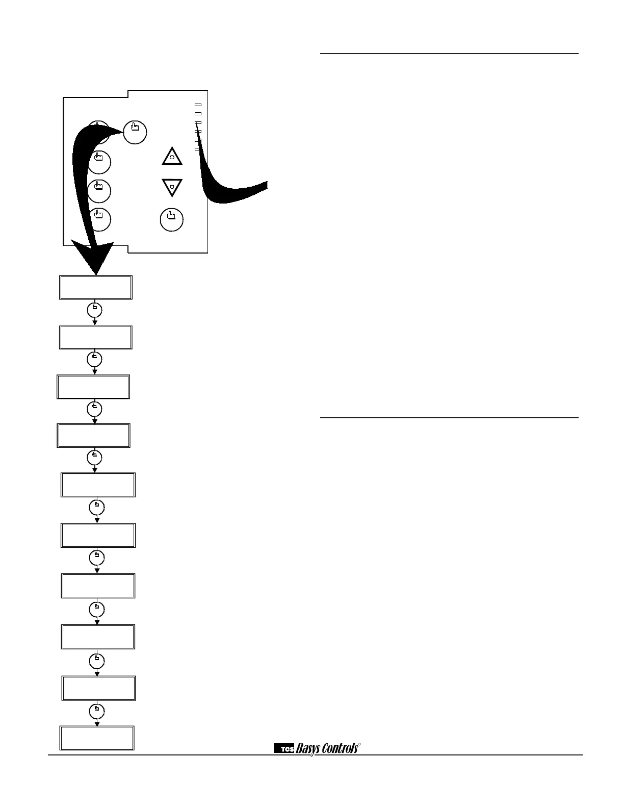
Service Screen. This message may be fol-
lowed by any or all of the following: CHECK
FILTER, CHECK FAN, DISCHARGE HIGH,
DISCHARGE LOW, or CHECK DI2.
Discharge Air Temperature Screen.
Shows discharge air temperature if sensor is
used.
Outdoor Air Temperature Screen. Shows
outdoor air temperature if sensor is used. (Not
available on the SZ1024.)
Override Status Screen. Shows whether the
override is active and if so, how many minutes
remaining.
Compressor Stages Status Screen. Shows
the status of the first and second stage com-
pressors.
Auxiliary Heat Stages Status Screen.
Shows the status of the first and second
stages auxiliary heat.
Reversing Valve and DI1 Status Screen.
Shows the position of the reversing valve as
either open or closed and the status of the fan
interlock or DI1.
DI2 and DI3 Status Screen. Shows the cool
lockout into DI2 or DI2 status and filter status
or DI3 status.
Main Monitoring Screen. (Date not shown on
SZ1024.)
SERVICE SCREENS
Continually pressing the service status button allows
more extensive monitoring. The screens are shown
below.
MON
72F
12:00 AM
DISCHARGE AIR
55F
OUTDOOR AIR
75F
SERVICE STATUS
OK
TEMP
1.
2.
3.
TEMP
service
status
service
status
service
status
service
status
fan
Occup ied
Heating
Cooling
Fan
Ser vic e
Program/
COOLER
WARMER
Data
swit ch
service
status
system
swit ch
program
setup
clock
setup
override
11-19-01
Main Monitoring Screen. Press the service
button to access the following screens. (Date
not shown on SZ1024.)
Shown below
LED Description
Six LEDs on the face allow the occupant to view the
current operating status of the thermostat.
OCCUPIED
This LED will be lit whenever the unit is operating in
the occupied mode.
HEATING
This LED will be lit when any heat output is closed.
COOLING
This LED will be lit when any cooling output is closed.
FAN
This LED will be lit when the fan output is closed.
SERVICE
This LED will be lit when the high or low discharge
air limit has been reached, when the fan interlock has
indicated failure, or when the filter service or service
input are closed.
PROGRAM/DATA
This LED will be lit when the thermostat is within the
programming or clock setup menus. It will blink when the
unit is being accessed by a PC.
Additional monitoring is available by continually pressing
the service key.
Limiting Occupant Access
SETPOINT ADJUSTMENT
The occupant may temporarily change the occupied
heating and cooling setpoints +/- 5°F by factory default.
This setpoint change will remain until the end of the cur-
rent occupied period, at which time the program reverts
to the setpoints defined in programming. To change the
range of adjustment allowed, see programming step #
15.
OVERRIDE
The occupant has the ability to put the unit into occupied
mode by pressing the override button on the front. By
factory default, the unit will remain in the occupied mode
for 180 minutes. This value may be changed from 0 to
255 minutes in programming step # 16.
FAN SWITCHING
The option to allow the occupant to change the occu-
pied fan mode is allowed by factory default. To lock out
access to fan switching, see programming step # 8.
SYSTEM SWITCHING
The option to allow the occupant to change the system
mode is allowed by factory default. To lock out access to
system switching, see programming step # 6.
 Loading...