2800 LAURA LANE • MIDDLETON, WI 53562 • (800) 288-9383 • FAX (608) 836-9044 • www.tcsbasys.com
6
R
program
setup
DISCHARGE AIR
HIGH LIMIT: 125F
40.
program
setup
ENABLE OUTDOOR
AIR FUNCT.? YES
41.
program
setup
DISCHARGE AIR
LOW LIMIT: 45F
39.
program
setup
AUX HEAT STAGE 1
DIFF: 1F
32.
program
setup
TIMECLOCK OUTPUT
OCCUPIED=CLOSED
37.
program
setup
AUX HEAT STAGE 2
OFFSET: 3F
33.
program
setup
REV VALVE OUTPUT
FOR COOLING NC
35.
program
setup
SET CONTROL
MODE: P
36.
program
setup
AUX HEAT STAGE 2
DIFF: 1F
34.
program
setup
DELAY ON POWERUP
10 SECONDS
48.
program
setup
DI3 USED FOR:
FILTER SERVICE
47.
program
setup
SET DI2 SETPOINT
SHIFT: 00F
46.
program
setup
COOLING LOCKOUT
TEMP: 65F
42.
program
setup
DI1 USED FOR:
MONITOR
44.
program
setup
DI2 USED FOR:
MONITOR
45.
program
setup
HEATING LOCKOUT
TEMP: 70F
43.
program
setup
ENABLE DISCHARGE
AIR FUNCT.? YES
38.
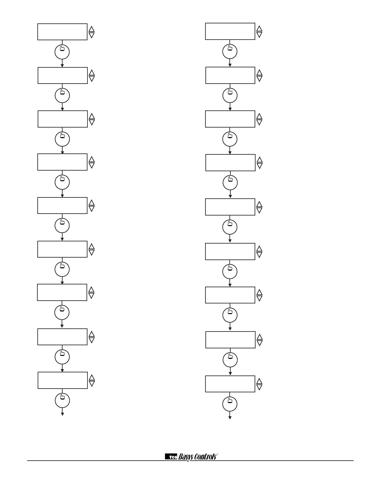
Auxiliary Heat Stage 1 Offset
Screen. Enter an offset value for cool
stage 1. This screen only appears if
auxiliary heat stage 1 is enabled.
Auxiliary Heat Stage 1 Differential
Screen. Enter a differential value for
auxiliary heat stage 1. This screen
only appears if auxiliary heat stage 1
is enabled.
Auxiliary Heat Stage 2 Offset
Screen. Enter an offset value for
auxiliary heat stage 2. This screen
only appears if auxiliary heat stage 2
is enabled.
Auxiliary Heat Stage 2 Differential
Screen. Enter a differential value for
auxiliary heat stage 2. This screen
only appears if auxiliary heat stage 2
is enabled.
Reversing Valve Output Screen.
Enter whether the reversing valve
output will be open (NO) or closed
(NC) for cooling.
Control Mode Screen. Enter whether
you want to control by temperature
only (P) or add a time factor (P+I).
Time Clock Output Screen. Choose
whether the auxiliary output will be
OPEN during occupied periods (and
closed during unoccupied periods)
or CLOSED during occupied periods
(and open during unoccupied peri-
ods).
Discharge Air Sensor Function
Screen. Choose whether or not you
are using a discharge air sensor
function. See setup instructions for
dipswitch settings which must also
be set.
Discharge Air Low Limit Screen.
Enter a discharge air low limit value.
This screen will not appear if the dis-
charge air function is disabled.
program
setup
AUX HEAT STAGE 1
OFFSET: 2F
31.
Discharge Air High Limit Screen.
Enter a discharge air high limit value.
This screen will not appear if the dis-
charge air function is disabled.
Outdoor Air Sensor Function Screen.
Choose whether or not you are using
an outdoor air sensor function. See
setup instructions for dipswitch settings
which must also be set. (Not shown on
the SZ1024.)
Cooling Lockout Screen. Enter an
outdoor air cooling lockout tempera-
ture. This screen will not appear if the
outdoor air function is disabled. (Not
shown on the SZ1024.)
Heating Lockout Screen. Enter an
outdoor air heating lockout temperature.
This screen will not appear if the out-
door air sensor is disabled. (Not shown
on the SZ1024.)
DI1 Choice Screen. Choose DI1 as
FAN PROVING or a MONITOR point.
Select MONITOR if unused.
DI2 Choice Screen. Choose DI2
as COOL LOCKOUT, or SERVICE
MONITOR. Select MONITOR if unused.
DI2 Shift Screen. Enter the setpoint
shift value. This screen will only appear
if DI2 is set to MONITOR.
DI3 Choice Screen. Choose FILTER
SERVICE, EXTernal OVERRIDE, or
EXTernal TIME CLOCK. Select EXTernal
OVERRIDE if unused.
Delay On Power up Screen. Enter
a value in seconds, such that when
the unit is powered up, all outputs are
delayed for this time period before they
are allowed to close.
 Loading...