LEGEND 3:
1. Bottom ventilation openings
2. Ground terminal for motor cable
3. Ventilation openings
4. Connector for management of motor thermal probes and simulated encoder (M4)
5. Terminal board for motor and braking resistor connection
6. Case
7. Feedback boards (option)
8. Removable plastic cover
9. Digital and analog I/O connector (M1)
10. Serial port 485/422 (J1)
11. Push buttons to set and display the parameters
12. Fixed plastic cover
13. Upper mounting bracket
14. Drive status parameters and display
15. Connector for hand-held or remote keypad
16. Connector for parametrization key
17. Frequency input connector (M2)
18. Digital and analog I/O connector (M3)
19. Fieldbus connector (option)
20. Lower mounting bracket
21. Ground terminal
22. Top ventilation openings
23. Line input terminal
24. Power connector for regulation board or output +24V (X3)
25. +24V power supply connector for cooling fans (X8)
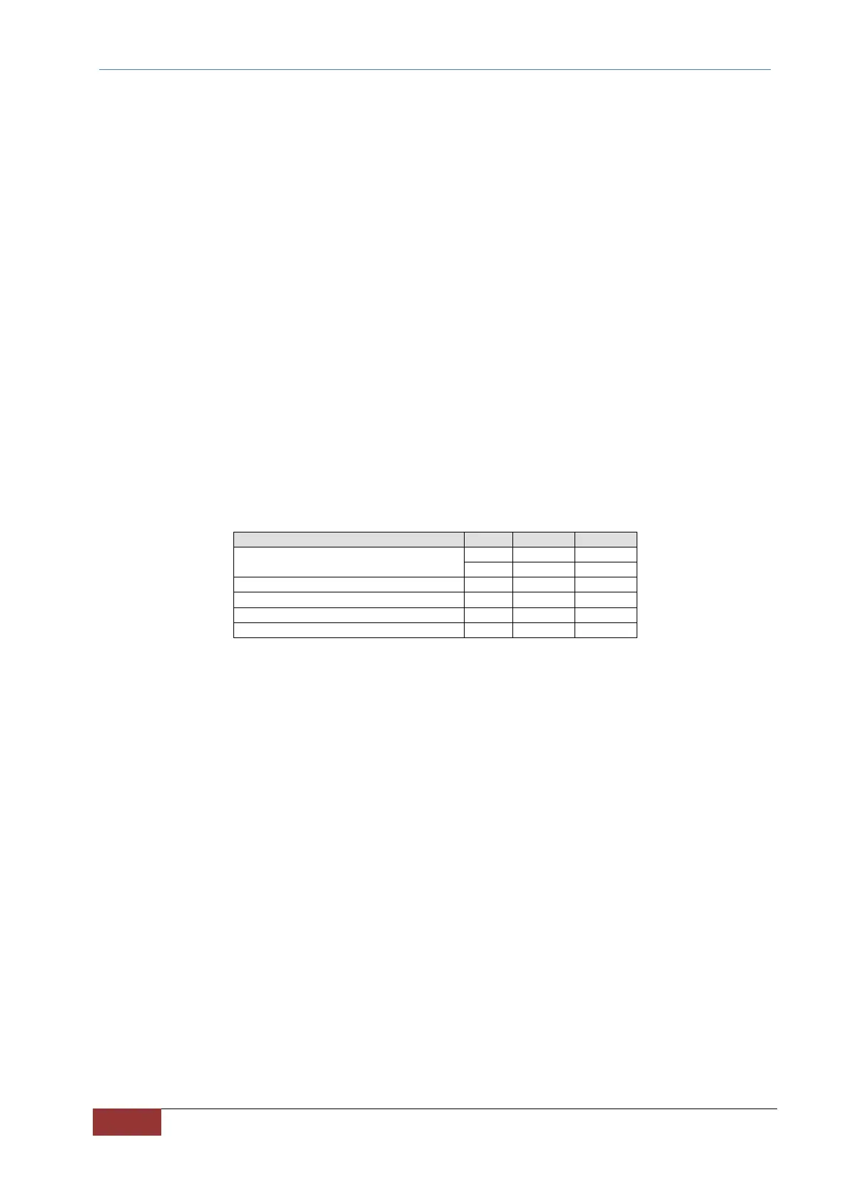
TAB. 2A – Mechanical dimensions and weight of OPDE SD 22 and 32
 Loading...