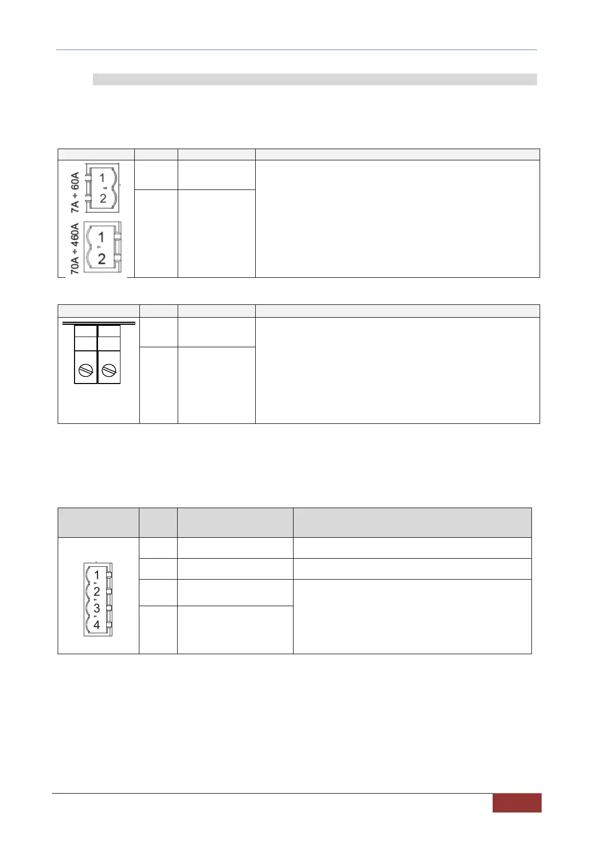
7.2.4 POWER SUPPLIES
OPDE DC-DC requires two auxiliary power supply voltages: one for the power supply of the control (adjustment) side
and driver, and one for the power supply of the cooling fans. The adjustment and driver power supply must be
provided through the removable terminal X3, which is located on the front of OPDE DC-DC. The power supply of the
fans, instead, must be provided through the bulkhead terminals on the bottom side of the converter.
Control side and drivers power supply.
Power supply voltage: 24Vdc (22÷26Vdc).
7A – 60A Maximum absorbed current 1 A
70A – 460A Maximum absorbed current 1.6 A
TAB. 12 – Connector X3
Heat sink cooling fans power supply.
Power supply voltage: 24Vdc (22÷26Vdc).
Maximum absorbed current:
OPDE SD 7, 15, 22 0.2 A
OPDE SD 32 0.4 A
OPDE SD 48, 60 0.6 A
OPDE SD 70, 90, 110 1.5 A
OPDE SD 150, 175 2.5 A
OPDE SD 220, 250 3.5 A
OPDE SD 310, 370, 460 5.0 A
TAB. 13 – Fan terminal
X8 is just the power supply terminal of the fans. To enable the operation of the fans, it is necessary to connect a
voltage of 24V between the terminals 3 and 4 of connector X7 (fig.15 left side).
Using a generic logical output LOx set as "O32 - Enable DC-DC fans" and following the connection of (fig.15 right
side) it is possible to control the switching on of the fans based on the temperature of the heat sink.
Enabling input of the ventilation fan.
+24V ±10% - min. 200mA
TAB. 14 – Internal fans enabling input