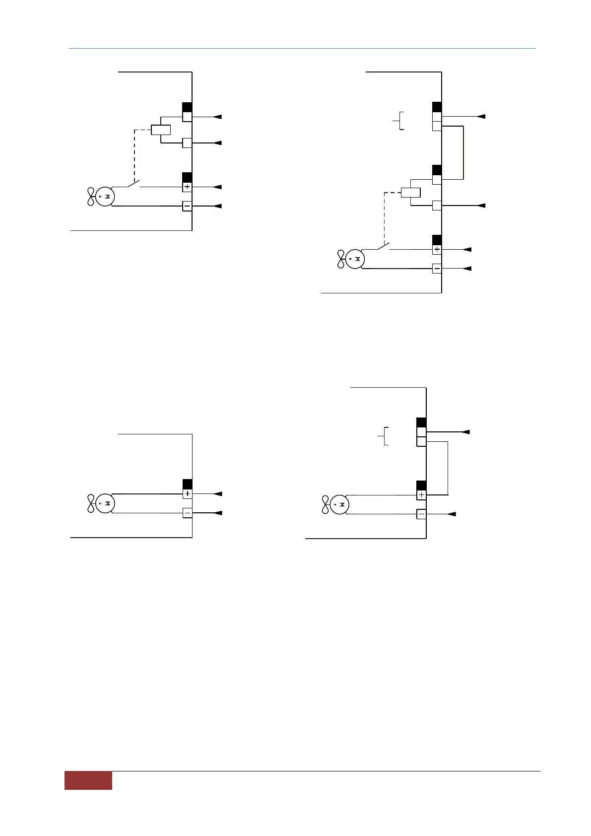
FIG. 16 – Example of connection of the fans power terminal (X8) and fans enabling terminal (X7). On the left, connection
with fans always on. On the right, connection with fans controlled via L.O.x logical output set as "O32 – Enable DC-DC
fans" (automatic switching-on depending on the heat sink temperature).
FIG. 17 – Example of connection of the fans power terminal (X8) and fans enabling terminal (X7) for size 22 ÷ 60A. On the
left, connection with fans always on. On the right, connection with fans controlled via L.O.x logical output set as "O32 –
Enable DC-DC fans" (automatic switching-on depending on the heat sink temperature).
Use only digital output with relay L.O.2 or L.O.4.
0V
-X8
-M1/M2
24V
L.O.x
/L.O.x
O32 - ENABLE AFE FANS
0V
24V
0V
-X8
-X7
4
3
-M1/M2
24V
L.O.x
/L.O.x
O32 - ENABLE AFE FANS