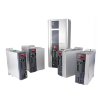
LEGEND FIG. 5:
26. Case
27. Extractable cooling fan
28. Feedback boards (option)
29. Removable plastic cover
30. Fixed plastic cover
31. Digital and analog I/O connector (M1)
32. Serial port 485/422 (J1)
33. Connector for parameterization key
34. Push buttons to set and display the parameters
35. Drive status parameters and display
36. Connector for hand-held or remote keypad
37. Frequency input connector (M2)
38. Digital and analog I/O connector (M3)
39. Fieldbus connector (option)
40. +24 VDC output connector (X6)
41. +24 VDC regulation board power supply (X3)
42. +24VDC connector for enabling cooling fans supply (X7)
43. Anybus connector (X5) (option)
44. Connector for management of motor thermal probes and simulated encoder (X4)
45. Lifting eyebolts
46. Upper shield bracket
47. Lower shield bracket
48. Upper mounting bracket
49. Lower mounting bracket
50. Top ventilation openings
51. Grid input power connections
52. Output power connections (motor side)
53. Positive and negative DC bus and braking power connections
54. Internal +24V power supply connector for cooling fans (X8)
TAB. 4C – Mechanical dimensions and weight of OPDE SD 70, 90, 110 and 150
 Loading...