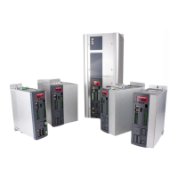
LEGEND FIG. 6:
1. Case supporting shoulders or wall hooking
2. +24V power supply connector for cooling fans (X8)
3. Case
4. Cooling fans of the power module
5. Panel covering the power terminals
6. Mounting holes
7. Feedback boards (option)
8. Removable plastic cover
9. Fixed plastic cover
10. Digital and analog I/O connector (M1)
11. Serial port 485/422 (J1)
12. Connector for parameterization key
13. Keys for setting and displaying the parameters
14. Display for converter status and parameter display
15. Connector for handheld or remote keypad
16. Fixed cover
17. Frequency input connector (M2)
18. Digital and analog I/O connector (M3)
19. +24VDC connector for enabling cooling fans supply (X7)
20. +24 VDC regulation board power supply (X3)
21. +24 VDC output connector (X6)
22. Connector for the management of the temperature sensors of the motor and simulated encoder (X4)
23. Anybus connector (X5)
24. Fieldbus connector (option)
25. Cooling heat sink fins
26. Ground terminal
27. Holes for cable/bar passage
28. Upper side venting openings
TAB. 3D – Mechanical dimensions and weight of OPDE SD 175, 220, 250