49
Open Drive - Mod. 03A ÷ 460A
Istruzioni per l’installazione / Installation instructions
Rev. 3.1 - 29.04.09 - IT (originali) / EN (Translations from original instructions)
S.p.A.
5.2.14- ALIMENTAZIONI
Solo per versione A.
INSTALLAZIONE / INSTALLATION
5
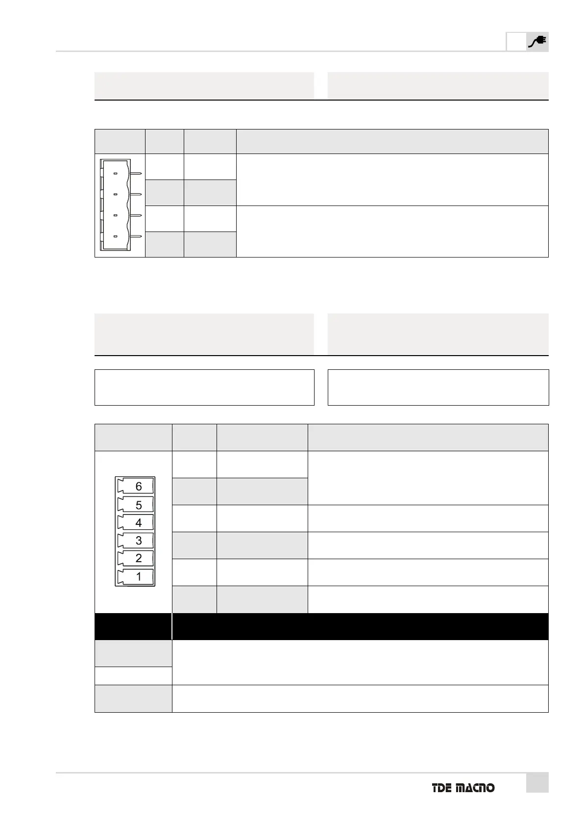
M5 PIN
FUNZIONE
FUNCTION
DESCRIZIONE / DESCRIPTION
1 +24VREG
Ingresso Alimentazione +24VDC scheda regolazione e controllo (v. nota 3 TAB. 3B).
+24VDC Supply for regulation and control card (s. note 3 TAB. 3B).
2 0VREG
3 +24VDR
4 0VDR
Ingresso Alimentazione +24VDC accenditori IGBT (v. nota 4 TAB. 3B).
+24VDC Supply for IGBT drivers (s. note 4 TAB. 3B).
TAB. 12
(Alimentazioni / Supply)
M6 PIN FUNZIONE DESCRIZIONE / DESCRIPTION
1 /PTC Bimetallic
Ingresso sonda termica motore (PTC o NTC).
Motor thermal probe input (PTC or NTC).
2 PTC Bimetallic
3 PT100+
Ingresso PT100 (altrimenti collegato a PT100_ESCL).
PT100 Input (otherwise connected to PT100_ESCL).
4 PT100_ESCL
Esclusione PT100 (da collegarsi a PT100+).
PT100 Excluded (to be connected to PT100+).
5 PT100-
Ingresso /PT100 (altrimenti non collegato).
/PT100 Input (otherwise not connected).
6 SHIELD
SENSORE DESCRIZIONE COLLEGAMENTO / CONNECTION INSTRUCTIONS
PTC o
Bimetallica On/Off
Collegare la PTC (NTC) tra i PIN 1 e 2 e cortocircuitare i PIN 3 e 4.
Connect PTC (NTC) between PIN 1 and 2 and short-circuit PIN 3 and 4.
NTC
PT100+
Collegare la PT100 tra i PIN 3 e 5 e cortocircuitare i PIN 1 e 2.
Connect PT100 between PIN 3 and 5 and short-circuit PIN 1 and 2.
TAB. 13
(Gestione sensore termico motore / Management of motor thermal sensor)
N.B.: FARE RIFERIMENTO AL FASCICOLO “OPZIONI
RETROAZIONE” PRESENTE NEL MANUALE
UTENTE SPECIFICO.
5.2.14- POWER SUPPLY
Only for A version.
5.2.15- GESTIONE SENSORE
TERMICO MOTORE
5.2.15- MANAGEMENT OF MOTOR
THERMAL SENSOR
N.B.: PLS. REFER TO DOCUMENT “FEEDBACK
OPTIONS” IN THE APPROPRIATE USER MANUAL.