Do you have a question about the TDE MACNO DVS200 and is the answer not in the manual?
Symbol indicating potential injury or death if precautions are not followed.
Symbol indicating potential equipment damage if precautions are not followed.
Symbol indicating essential procedures for correct functioning.
Symbol for relevant information or conditions.
Essential safety guidelines for connecting power and ground.
Core operational features and capabilities of the DVS drive.
Extended features and functionalities for advanced control.
Optional accessories or configurations for the DVS drive.
Guidelines for handling and transporting the drive safely.
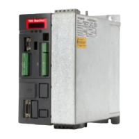
Identification and description of the drive's internal components.
Overview of the drive's overall technical characteristics.
Guidance on connecting the drive to mains power and motor.
Physical dimensions and mounting requirements for the drive.
Required clearances for proper ventilation and installation.
Guidelines for selecting and connecting compatible motors.
Procedures for safely accessing the drive's connection terminals.
Details on the drive's power supply and connection components.
Information on the drive's control circuitry and main board.
Details on connecting and using the RS 485 serial communication.
Common wiring diagrams for drive connections.
Information on inductive chokes and filters for noise suppression.
Explanation of the drive's braking functions and configurations.
Required waiting period after disconnecting power before servicing.
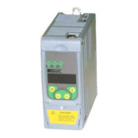
Explanation of the front panel buttons and status indicators.
How to move through the drive's parameter menus using the keys.
Step-by-step guide for basic drive parameter configuration.
A comprehensive list of all drive parameters and their functions.
Parameters for displaying drive information and status.
Parameters for initial drive configuration and setup.
Parameters for digital inputs, outputs, and analog signals.
Parameters for frequency reference and ramp generation settings.
Core drive parameters for operation, motor data, and V/F settings.
Parameters for PID control, application-specific functions, and tuning.
Commands for saving, loading, resetting, and tuning drive parameters.
Access to advanced or hidden parameters via serial or field bus.
Detailed explanation of the Modbus protocol structure and operation.
Structure of Modbus messages, including address, function code, and data.
Specific Modbus functions implemented for DVS drive control.
Handling and interpretation of transmission and operating errors.
Setting up serial communication parameters and protocols.
How alarm conditions are displayed and identified on the drive.
Procedures for resetting drive alarms via keypad or digital input.
A table detailing various alarm events and their descriptions.
Explains the different validity fields related to EMC directives.