User Manual Chapter 7 - Parameters Description 93
This parameter takes into account the sum of all the reference frequencies and frequency variables of the drive,
deriving by :
Speed references, Slip compensation, PID regulator
P.081 Min output freq (Minimun output frequency)
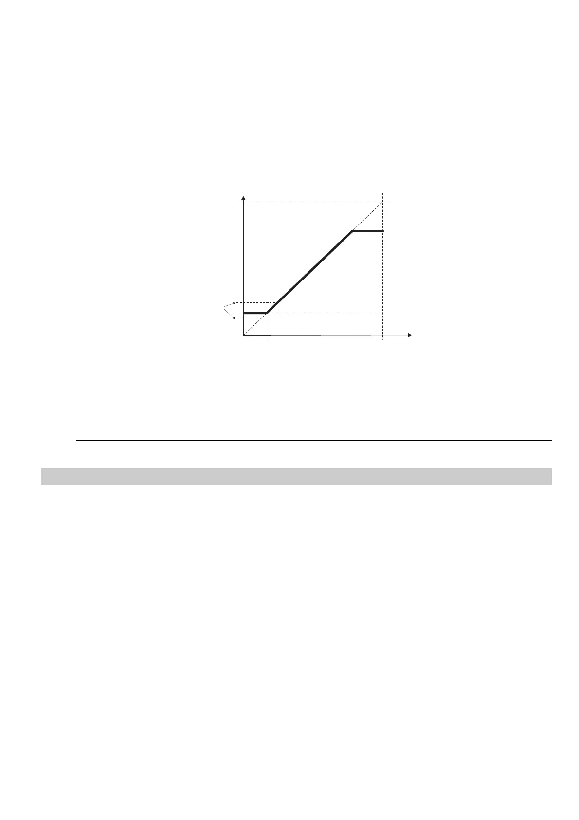
Minimum value of output frequency, under which no reference regulation has effect.
It is expressed as percentage of Max output freq (P.080).
The parameter is correlated to the Min ref freq (F.021), as reported in the figure below.
F out
Max output freq (P.080)
Max ref freq (F.020)
Min ref freq (F.021)
Set frequency
Min output freq (P.081)
(A)
(B)
Figure 7.6.7: Min & Max Reference Frequency
A signalling of the "output frequency" status is available on the digital output as "Out freq<set".
Code Name [Code] & Function. Default MIN MAX Unit Variation IPA
P.080 Max output freq 100 0 110 % of F.020 417
P.081 Min output freq 0.0 0.0 25.0 % of F.020 0.1 418
Slip Compensation
P.100 Slip compensat (Slip compensation)
If an induction motor is being used, the mechanical speed will vary with the load due to the slip of the motor.
In order to adjust for this speed error the slip compensation can be used.
During this calibration, make sure that the drive is not in a current limit condition.
If this compensation is set too high it can cause instability.
The changing will be carried out as a percentage of the nominal slip, calculated when set the motor plate date.
The Slip compensation will act directly on the output frequency of the drive. For this purpose the parameter
Max output freq (P.080) expressing the percentage of the Max ref freq (F.020), has to be set to a value
including:
Max ref freq value + Slip compensat value.
See chapter "PARAMETERS", section "Output Frequency Limit".
The Slip compensation must be disabled when a multiple motor connection is being used.
P.101 Slip comp filter (Slip compensation filter)
It is the response time (in seconds) for the reaction of the function.
Increasing this value helps damping oscillations that may arise with load steps (especially negative ones).