30 Chapter 5 - Electrical Connections User Manual
5.5. Typical Connection Schematics
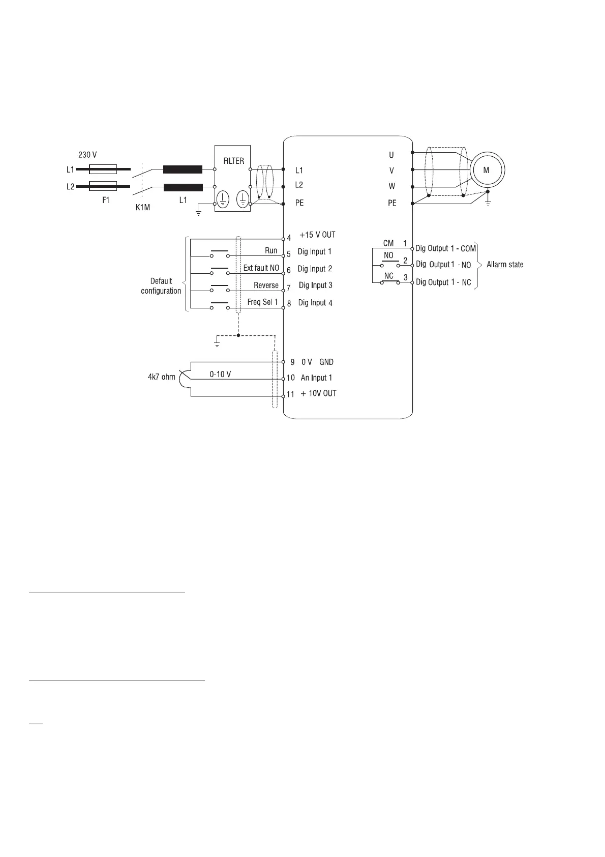
5.5.1. DVS drive connections
Figure 5.5.1.1: Control via terminals, typical connection schematic
NOTA!
The control input connections shown above represent the most common connection solution for NPN
control. See below for further examples.
5.5.2. Design constraints
The wires for the analog signals must be shielded (connection to terminals 9, 10, 11).
The shielding must be connected to the PE terminal at only one side.
Grounding of the reference potential
The terminal wire shielding potential must normally be grounded. Jumper J7 links the potential of terminal 9 (GND 0V,
control reference) to protective earth (PE).
If a single installation comprises more than one drive, the different potentials of their terminal wire shields must be connected
in common to the control panels ground bus.
Direct connection to PLC inputs/outputs
Observe the following points if control commands or references are obtained directly from PLC inputs/outputs.
The PLCs 0V terminal must normally be grounded. if this is done, the drive control reference potential (J7 NOT fitted) must
not be grounded.
To ensure good immunity to interference, connect a 0.1mF 250V DC capacitor between terminal 9 and
ground. If more than one drive is present in a single installation, this must be done for each individual
drive.