User Manual Chapter 5 - Electrical Connections 27
5.3. The control section
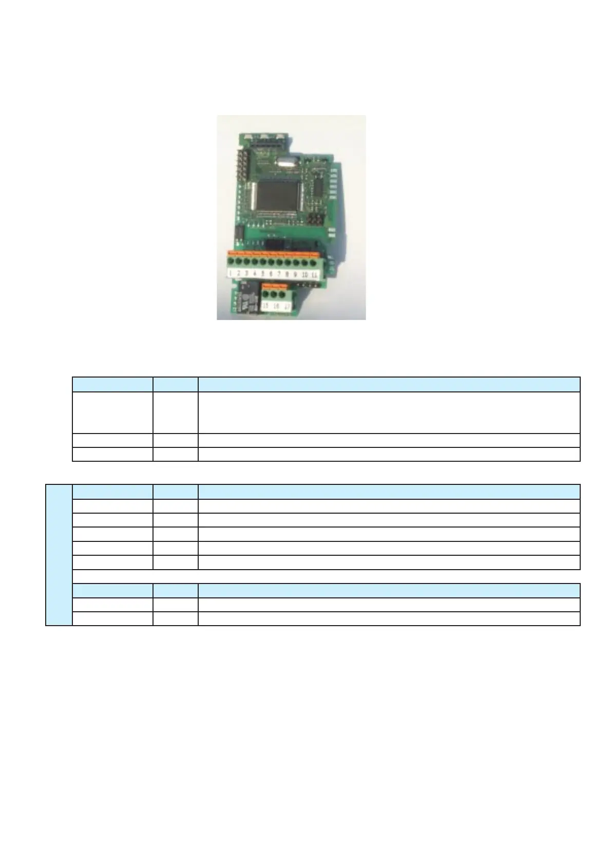
5.3.1. The A313-XX control card
A313XX
LED Colour
D1 yellow Lit = drive power
Flashing = parameters changed but not saved
Off = attempting to change unmodifiable parameter in Run
D2 green Lit = Run command enabled and active
D3 red Lit = drive in alarm state
Connector PIN N°
C1 6 Programming key connector
C2 6 Keypad connector
C3 7 Control terminals
C4 3 Serial line terminals
S1 4 Slot for optional serial line
Jumper Default
J5 0 Transforms analog voltage input into current input
J7 0 Links control card 0V to ground
Function
DVS
Function
Function
D1 D2 D3
C1
HIGH VOLTAGE (DC-link)
C2
OPTO-INSULATION BARRIER- - - - - - - - - - - - - - - - - - - - - - - - - - - - - - - - - -
C3
LOW VOLTAGE (motor side)
J5 - J7
S1 C4
Table 5.3.1.1: LEDs, jumpers and connectors on the A313-XX
Figure 5.3.1.1: The A313-XX control card