Do you have a question about the TDE MACNO OPEN DRIVE and is the answer not in the manual?
Emphasizes the need for authorized operators to read and understand the entire manual.
Explains general danger signs, text formatting, and symbols used in the manual.
Defines authorized operators and their responsibilities for safe operation and maintenance.
Details the procedure to ensure the device is safely powered off before maintenance.
Lists common abbreviations used throughout the document for clarity.
States that the manual content is reserved property of the manufacturer.
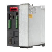
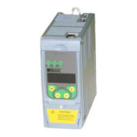
States the official name of the apparatus being described.
Explains the meaning of each letter in the 'Type' field of the CE marking/data plate.
Details specific product versions based on configurations like voltage and control.
Identifies main components and provides overall dimensions for different models.
Presents detailed technical specifications for various Open Drive models.
Specifies the designed and manufactured intended use for the Open Drive unit.
Outlines the sequence of operations for using the Open Drive unit.
Details strict limitations and forbidden applications to ensure safety and efficiency.
Describes how the Open Drive is shipped to the customer.
Emphasizes checking packaging for damage and proper acceptance procedures.
Provides crucial safety warnings for lifting and manual handling of the package.
Guides on unpacking the drive and responsible disposal of packaging materials.
Recommends conditions for storing the Open Drive to maintain its integrity.
Specifies temperature, humidity, and condensation limits for storage.
Details the steps needed to prepare the drive for operation after a storage period.
Provides essential instructions for positioning, securing, and accessing the Open Drive.
Details all necessary steps for making safe and correct electrical connections.
Explains the power stage components and operation, including rectification and IGBTs.
Specifies requirements for connecting the drive to the power mains, including chokes.
Describes the soft start circuit used to limit inrush current during power-up.
Provides instructions for connecting the motor, including cable sizing and safety precautions.
Details the mandatory grounding requirements for safe operation and protection.
Explains the braking circuit and the use of external resistors for energy conversion.
Describes the separate power supplies for regulation and IGBT drivers in A-version units.
Explains how drives can be powered by a common bus, detailing advantages.
Illustrates the physical layout of power connections for mains and motor.
Provides an overview of the different logic connectors and their pin assignments.
Details the pin assignments and functions for digital and analog logic I/O.
Describes the terminals and functions for frequency input signals.
Details the pin assignments and functions for digital and analog I/O.
Specifies power supply connections for regulation and IGBT drivers for A-version units.
Explains how to connect and manage motor thermal sensors (PTC, NTC, PT100).
Lists the default settings for inputs and outputs for easy setup.
Provides instructions for connecting the serial communication line via connector J1.
Explains how the drive status and alarms are displayed, with a correspondence table.
Details required line inductances and choke codes for various drive models.
Provides a table for selecting appropriate ultra-fast fuses based on drive model.
Details braking chopper specifications, resistor values, and TDE Macno codes.
Lists motor-side options, including impedance values and TDE Macno codes.
Step-by-step guide for commissioning the drive using pre-existing parameter recipes.
Lists relevant European Directives and Norms that the drive complies with.
Guidelines for selecting fuses, input chokes, and braking resistors based on standards.
Provides measures to minimize electromagnetic interference between devices and cables.