28 Chapter 5 - Electrical Connections User Manual
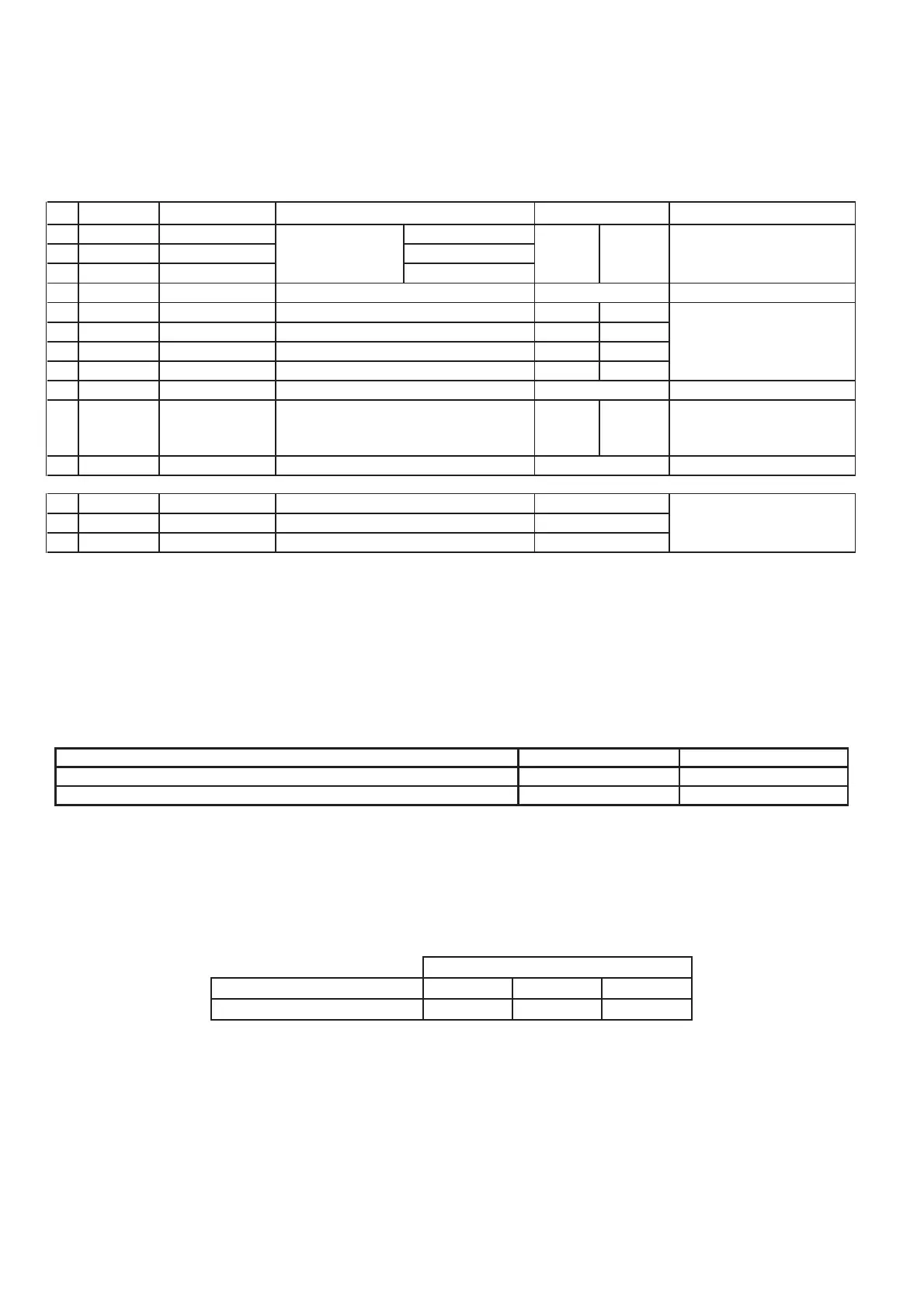
5.3.2. Control card terminal identification
Figure 5.3.2.1: Control card terminal identification
No. Terminal Description FUNCTION Signal type
1 REL-CM Digital output 1 Common
2 REL-NO Digital output 1 Norm.Open
3 REL-NC Digital output 1 Norm.Closed
4 +15V +15 V OUT Auxiliary power for digital inputs 15V +/-5% 300mA
5 IN 1 Digital input 1 Programmable digital input 1 I-100=1 RUN
6 IN 2 Digital input 2 Programmable digital input 2 I-100=3 EF
7 IN 3 Digital input 3 Programmable digital input 3 I-100=2 REV
8 IN 4 Digital input 4 Programmable digital input 4 I-100=7 Freq.Sel.
9 GND 0 V Reference ground for analog input
Programmable analog input
11 +10V + 10 V OUT Auxiliary power for potentiometer 10 V +/-3% 50mA
15 GND 0V Reference ground
16 FB + Link + Serial line +
17 FB - Link - Serial line -
0-10V, 0-20mA, 4-20
mA
RS 485
I-200=1 0-10V10
IN AN 1
Analog input 1
Switching capacity: 230
Vac,0.2A;30Vdc,1A
7mA at 15V opto-
couplers for PNP logic,
active connected to
+15V
Default
Programmable
relay output
I-100=1 ALARM
Maximum wire sections for control card terminals
Table 5.3.2.1: Maximum wire sections for control card terminals
Control connection data
[mm
2
]/[mm
2
]/AWG
0,22-1 / 0,22-1 / 26-18
[mm
2
]
0,25 - 0,34 / 0,25 - 0,34
[mm]
10
Rigid / Flexible / wire size
Flexible with spade end with/without insulating collar
Stripping length
Maximum wire length
Table 5.3.2.2: Maximum wire length
0,5 0,75 1
30 60 90
Wire section [mm2]
Maximum length [m]
Maximum wire length