1-30 System 3
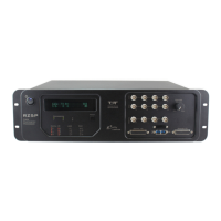
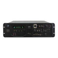
RZ5P Fiber Photometry Processor
BNC connectors on the front panel labeled Digital. See “RZ5P Technical
Specifications” on page 1-31, for the DB25 pinout and BNC channel mapping.
See the
Synapse Manual
for information on enabling digital I/0 and configuring data
direction.
The RZ5P digital I/O ports have different voltage outputs and logic thresholds
depending on the type. Below is a table depicting the different voltage outputs and
thresholds for both type.
LEDIndicators
The RZ5P contains 16 LED indicators for the analog and digital I/O. These
indicators are located directly below the VFD and DSP status LEDs. They display
information relative to the various analog and digital I/O. The following tables
illustrate the possible display options and their associated descriptions.
DigitalI/O
These LEDs indicate the state of the 8 bit-addressable I/O of byte C.
AnalogI/O
These LEDs indicate state of the ADC and DAC channels.
Digital I/O Description DB25 BNCs Notes
Byte A bits 0 - 7 Yes No byte addressable
Byte B bits 0 - 7 Yes No byte addressable
Byte C bits 0 - 7 Yes Yes* bit addressable
*Note: Byte C Bits 0 - 3 are available via front panel BNCs
Digital I/O Type
Voltage Output Voltage Input
logic high logic low logic high logic low
byte addressable 5 V 0 V ≥ 2.5 V 0 - 2.45 V
bit addressable 3.3 V 0 V ≥ 1.5 V 0 - 1.4 V
Light Pattern Description
Dim Green Bit is configured for output and is currently a logical low (0)
Solid Green Bit is configured for output and is currently a logical high (1)
Dim Red Bit is configured for input and is currently a logical low (0)
Solid Red Bit is configured for input and is currently a logical high (1)
Light Pattern Description
Off Analog I/O channel signal voltage is less than +/-100 mV