System 3 1-31
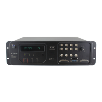
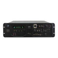
RZ5P Fiber Photometry Processor
UDPEthernetInterface(Optional)
The RZ UDP Ethernet interface is designed to transfer data to or from a PC. RZ
devices equipped with a UDP interface contain an additional port located on the back
panel. See “RZ-UDP Communications Interface” on page 1-63, for more
information.
RZ5PTechnicalSpecifications
Note: Specifications for amplifier A/D converters are found under the preamplifier's technical
specifications.
Dim Green Analog I/O channel signal voltage is less than +/-5 V
Solid Green Analog I/O channel signal voltage is between +/-5 V to +/-9 V
Solid Red Analog I/O channel clip warning (voltage greater than +/-9 V)
Light Pattern Description
DSP
Two 400 MHz DSPs, 2.4 GFLOPS peak per DSP
Memory
64 MB SDRAM per DSP
D/A
4 channels, 16-bit PCM
Sample Rate
Up to 48828.125 Hz
Frequency Response
DC - 0.44*Fs (Fs = sample rate)
Voltage Out
+/- 10.0 Volts, 175 mA max load
S/N (typical)
82 dB (20 Hz - 20 kHz at 9.9 V)
Output Impedance
10 Ohms
A/D
4 channels, 16-bit PCM
Sample Rate
Up to 48828.125 Hz
Frequency Response
DC - 7.5 kHz (3 dB corner, 2nd order, 12 dB per
octave)
Voltage In
+/- 10.0 Volts
S/N (typical)
82 dB (20 Hz - 20 kHz at 9.9 V)
Input Impedance
10 kOhms
Fiber Optic Port
One input for PZ5, PZ2, PZ3 or PZ4, up to 32 channels
Digital I/O
8 programmable bits: 3.3 V, 25 mA max load
2 programmable bytes(16 bits): 5.0 V, 35 mA max load