1-32 System 3
RZ5P Fiber Photometry Processor
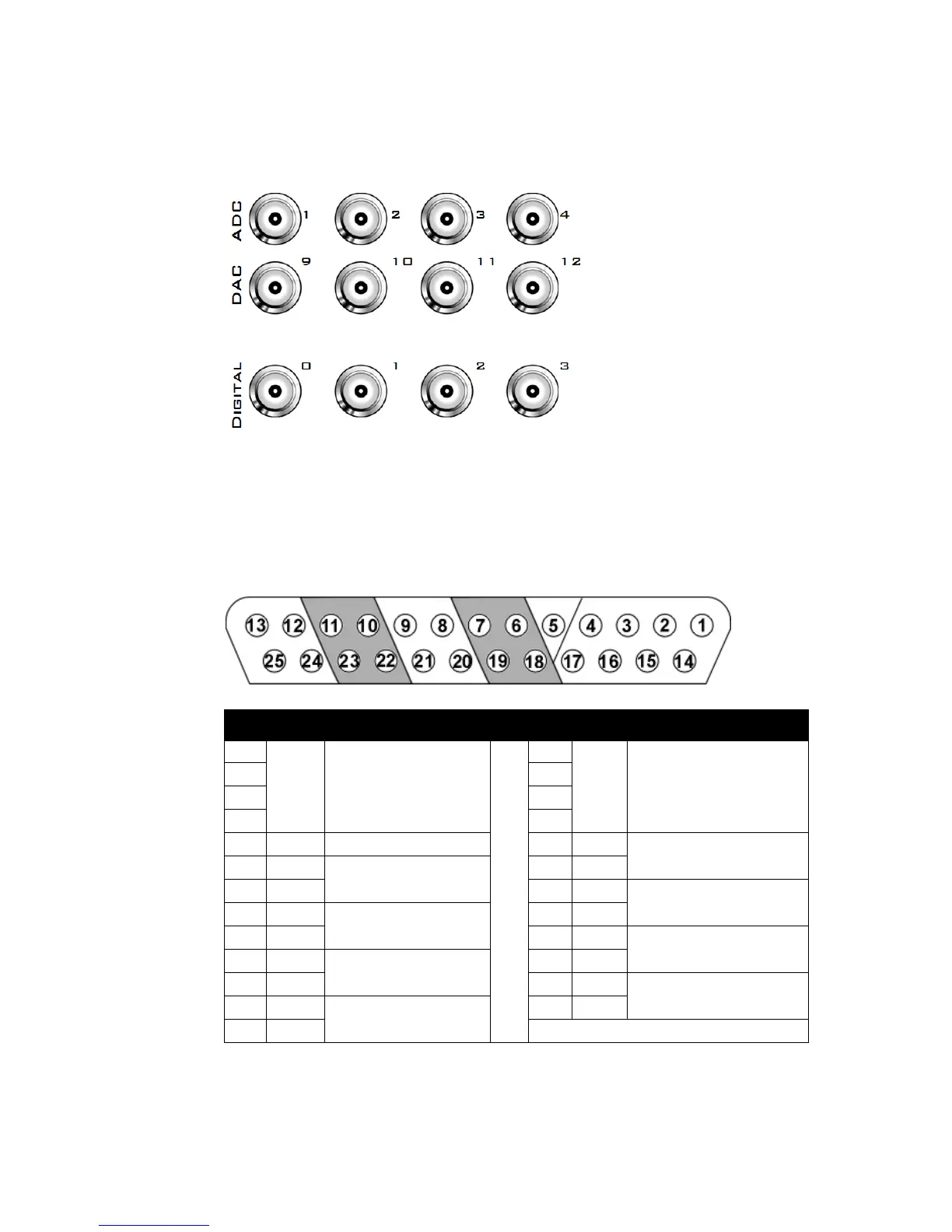
BNCChannelMapping
Please note channel numbering begins at the top left block of BNCs for both analog
and digital I/O and is printed on the face of the device to minimize miswiring.
DB25AnalogI/OPinout
Pin Name Description Pin Name Description
1 NA Not Used 14 NA Not Used
215
316
417
5 AGND Analog Ground 18 A1 ADC
Analog Input Channels
6 A2 ADC
Analog Input Channels
19 A3
7 A4 20 NA Not Used
8 NA Not Used 21 NA
9NA 22A9 DAC
Analog output Channels
10 A10 DAC
Analog Output Channels
23 A11
11 A12 24 NA Not Used
12 NA Not Used 25 NA
13 NA
Maps to:
Ch 1-4
Ch 9-12
Port C
Digital I/O
Analog Out
Analog In
Bits 0-3
Analog Out Analog In AGND