18-14 System 3
PP24 Patch Panel
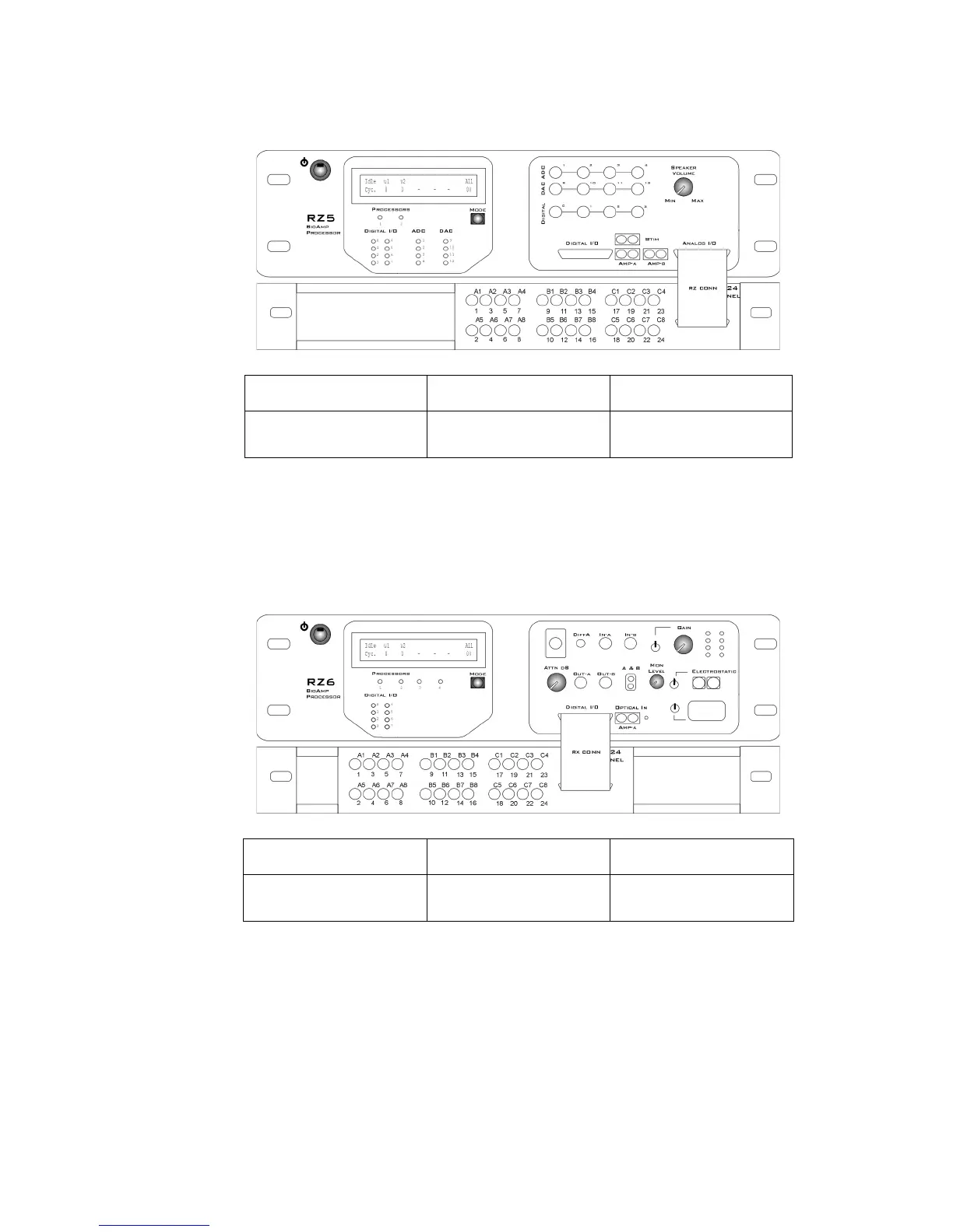
The diagram below maps the RZ5 or RZ5D Analog I/O connection to the PP24.
MappingRZ6I/O
Note: The PP24 is mounted below the RZ6.
The diagram below maps the RZ6 Digital I/O connection to the PP24.
A1-A8, B5-B8, C5-C8 B1-B4 C1-C4
Not Used Analog Input
Channels 1-4
Analog Output
Channels 9-12
A1-A8 B1-B8 C1-C8
Bit Addressable Digital I/O
Channels 0-7
Digital I/O, Byte A
Channels 0-7
Digital I/O, Byte B
Channels 0-7