System 3 18-25
PM2Relay Power Multiplexer
PM2R‐ControllingSignalPresentation
The circuits described here use typical techniques for controlling the signal
presentation when using a PM2R. These circuits have been designed as tutorials and
will need to be modified to meet the needs of the individual researcher.
ControllingthePM2RwithBitOuts:
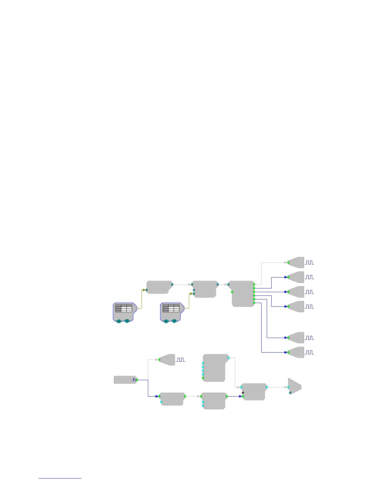
In this example several BitOuts are used to control the PM2R (via an RP2.1) from
within RPvdsEx. The bit pattern is generated by two DataTable components.
DataTables are commonly used to send values from the PC to the RP devices.
While working in RPvdsEx, the selection can be changed by clicking the green up
and down arrows near the bottom edge of the components. The first DataTable
(Channel Select) stores the values for the channel number. Channel numbers start
at zero and go to fifteen. Each RP2.1 is capable of controlling up to four PM2R
devices. The second DataTable (DeviceSelect) stores the values for the device ID.
The values in the table are 0 (device 0), 16 (device 1), 32 (device 2), and
48 (device 3). The iScaleAdd is used to add the integer values from both tables
and the ToBits component changes the resulting integer to the bitcode pattern. The
first four bits are used to select the channel number and the last two bits are used
to select the device ID.
A software trigger is used to change devices and initiate a tone burst of 100
milliseconds duration. The software trigger causes the Schmitt trigger to open a gate
for 100 milliseconds. The Schmitt trigger is delayed by one millisecond relative to the
channel select. This removes the transient associated with the relays.
hannel Sele
[1:1,0]
evice Sele
= 0
iScaleAdd
SF=1
Shft=0
[1:2,0]
b5
b4
b3
b2
b1
ToBits
Rst=0
[1:3,0]
b0
Bi
Bi
Bi
Bi
Bi
Bi
[1:14,0]
M=32
[1:15,0]
Src=Soft1
Bi
[1:16,0]
M=64
TTLDelay
Tdel=1
[1:18,0]
Schmitt
Thi=100
Tlo=10
[1:19,0]
Cos2Ga te
Trf=10
Ctrl =Cl osed
[1:22,0]
Tone
Amp=1
Shft=0
Freq=1000
Phse=0
[1:21,0]
c
[1:23,0]
Ch=1
If signal play out occurs during the selection an
audible click w ill be heard, a TTLDelay component is
used to delay the start of the signal play out
A software
trigger sets the
channel and
device ID
Use the Channel Select DataTable
to select a channel:
0 selects channel 1
15 selects channel 16
Use the Device Select DataTable
to select the device:
0 selects device 1
16 selects device 2
32 selects device 3
48 selects device 4
These bits are
used to select the
device ID
These bits are
used to select the
channel number


 To Next Page