1.3.1 ONE POWER SUPPLY OPERATION:
Make sure the power supply is NOT energized while making electrical connections to the controller.
The output voltage of the TE Power Supply should not exceed the maximum desired input voltage of the
thermoelectric device, or the rated input voltage of the cooling assembly.
If voltage is not between 12 V to 36 V then a two power supply configuration is necessary.
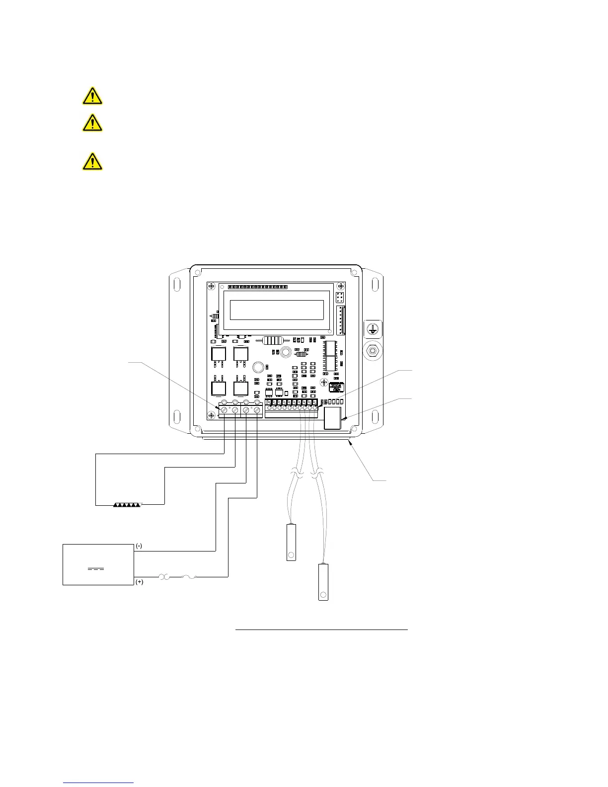
Connect the DC voltage power supply (output voltage: ≥12 V but ≤36 V) to the controller as follows:
a) Connect wire between Positive (+) terminal of the power supply and JP7-4.
b) Connect wire between Negative (-) terminal of the power supply and JP7-3.
c) See Section 1.4 for further information on connecting the TE device.
Connections, One Power Supply Operation
JP7 JP21 2 3 4 10 9 8 7 6 5 4 3 2 1
(+)
(-)
TE DEVICE
DC
POWER SUPPLY
OPTIONAL FUSE
THERMOSTAT AND OTHER
PROTECTIVE DEVICES
(CUSTOMER SUPPLIED)
OPTIONAL
SECONDARY
SENSOR
JP2-4 (+) and
JP2-3 (-)
CONTROL
SENSOR
JP2-1 (+) and
JP2-2 (-)
12 V, 36 V, 20 A maximum
JP7
PIN 1
JP2
PIN 1
WIRES MUST PASS THROUGH
RUBBER FACE-PLATE HOLES
NOTE: LID IS REMOVED TO SHOW
WIRE CONNECTIONS
USB COMMUNICATION PORT
to JP7-1
to JP7-2
to JP7-3
to JP7-4
≥ ≤