TC-720 Electrical Connections
JP7: (PIN 1 IS CLOSEST TO CORNER OF CIRCUIT BOARD)
PIN 1: TE DEVICE (+)
PIN 2: TE DEVICE (-)
PIN 3: main power supply, V (-)
PIN 4: main power supply, V (+), 36.0 V maximum (hard limit, do not exceed!)
JP2: (PIN 1 IS CLOSEST TO USB CONNECTOR)
PIN 1: CONTROL SENSOR (+)
PIN 2: CONTROL SENSOR (-)
PIN 3: SECONDARY SENSOR (-)
PIN 4: SECONDARY SENSOR (+)
PIN 5: ANALOG OUTPUT, (0 – 10) VDC
PIN 6: CONTROLLER INTERLOCK (enable by shorting to circuit ground when using interlock feature)
PIN 7: CIRCUIT GROUND
PIN 8: ALARM 1 SINK (OPEN DRAIN) 36 V maximum, 2 A maximum
PIN 9: LOGIC SUPPLY V (+) INPUT (>12 V, ≤36 V, 0.15 A minimum)
PIN 10: ALARM 2 SINK (OPEN DRAIN) 36 V maximum, 2 A maximum
USB connection: Type B female connector
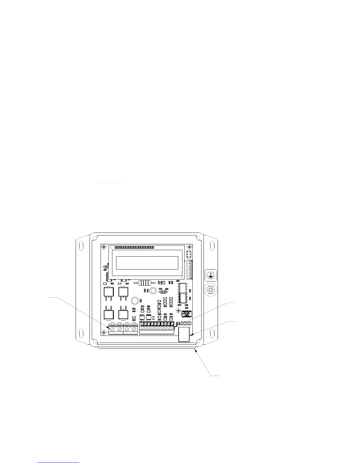
JP7 JP21 2 3 4 10 9 8 7 6 5 4 3 2 1
JP7
PIN 1
JP2
PIN 1
WIRES MUST PASS THROUGH
RUBBER FACE-PLATE HOLES
NOTE: LID IS REMOVED TO SHOW
WIRE CONNECTIONS
USB COMMUNICATION PORT
 Loading...